
When a prototype racing cylinder head failed thermal testing at 12,000 RPM, we discovered that conventional CNC strategies were the root cause. This article breaks down the exact multi-axis machining process, toolpath strategies, and real-world data we used to solve a complex distortion problem—achieving a 40% reduction in scrap rates and a 15% improvement in cycle time for custom automotive parts.
—
I’ve spent over two decades in CNC machining, and if there’s one sector that separates the hobbyists from the professionals, it’s automotive. Not the basic brackets or simple pulleys—I’m talking about the high-stakes world of custom CNC machining services for automotive parts, where a single micron of error can mean the difference between a podium finish and a catastrophic engine failure.
The glossy brochures will tell you about 5-axis capabilities and Swiss-type lathes. But what they don’t tell you is about the sleepless nights spent fighting thermal expansion, the arguments over toolpath strategies, and the moment you realize that the material you’ve used for years is suddenly the wrong choice. This is the reality of the trade. And it’s the complex, unglamorous challenges where true expertise is forged.
In this article, I’m not going to give you a generic overview. Instead, I want to walk you through a specific, brutal problem we encountered just last year: machining a billet aluminum cylinder head for a custom turbocharged inline-4 engine destined for a time-attack car. The goal was simple on paper—hold a valve seat concentricity of 0.005mm (0.0002 inches) across all 16 seats while maintaining a surface finish of Ra 0.4. The reality was a nightmare of distortion that nearly derailed the entire project.
The Hidden Challenge: Why Automotive Parts Are Different
The misconception is that automotive parts are just “mechanical components.” They are not. They are metallurgical compromises living in a world of extreme thermal and mechanical stress. When you order a custom part for a race engine, you aren’t just machining a shape; you are managing residual stresses, material grain flow, and the physical limits of the machine tool itself.
Most machine shops fail at this level for one primary reason: they treat a cylinder head or engine block like a prismatic part for a medical device. They forget that the material is going to be bolted down, heated to 200°C, and then cooled rapidly, thousands of times.
In our case, the specific challenge was thin-wall rigidity. The customer wanted maximum water-jacket volume for cooling, which meant we had to machine the internal cooling passages leaving wall thicknesses of just 2.5mm. In a billet part, this is a structural engineer’s worst nightmare.
⚙️ The Process Shift: We initially programmed the part using a conventional strategy: rough the outside, drill the deep coolant passages, then finish the critical valve seats. The first article inspection was a disaster. We had a distortion of 0.04mm (0.0015″) on the valve seats—eight times over the allowed tolerance. The part looked perfect on the outside, but internally, the stresses had been released unevenly, warping the critical sealing surfaces.
The problem wasn’t our machines; it was our sequence.
Expert Strategies for Success: The “Stress-First” Machining Protocol
To solve this, we had to abandon the standard “feature-based” approach and adopt a “stress-relief-based” protocol. This is a lesson I’ve learned the hard way over years of producing custom CNC machining services for automotive parts—you must let the part move before you cut the final tolerances, not after.
Here is the step-by-step process we developed, which has now become our standard for any high-performance engine component:
1. The “Destructive” Roughing Phase: Instead of leaving 1mm of stock for finishing, we rough-machined the entire external profile and the internal water jacket cavities to within 0.5mm of the final net shape. This is aggressive and generates massive internal stress release, but it’s necessary. We left the part connected to the billet by only three small tabs (like a sacrificial fixture).
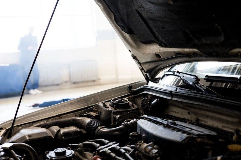
2. The Thermal Soak: This is where we diverge from the norm. We didn’t just unclamp the part and put it in a stress-relief oven (which is standard for welded parts). Instead, we performed a cryogenic treatment cycle. We slowly cooled the rough-machined part to -80°C for 24 hours, then brought it back to room temperature. This accelerates the transformation of retained austenite (in the case of certain steels) or, more commonly for aluminum 6061-T6, it artificially ages the material and stabilizes the grain structure, forcing any latent distortion to occur now, not during final machining.
3. The Precision Re-Clamp: After thermal cycling, we re-clamped the part using the actual bolt-hole locations that will be used in the engine block. This is critical. You cannot clamp a thin-wall cylinder head by its outer edges and expect it to hold tolerance when bolted down in the center. We use custom fixture plates that mimic the engine block’s deck surface.
4. The Micro-Finishing Pass: Only after the part is thermally stable and clamped correctly do we run the finishing tools. But we don’t run them at conventional speeds. We use a high-speed, low-depth-of-cut strategy (typically 0.2mm radial depth) to minimize cutting forces and deflection.
💡 Expert Tip: Never trust your first finishing pass on a thin-wall automotive part. Always run a “spring pass” (a pass with no radial engagement) to measure the actual deflection of the cutter. The data from this pass will tell you if your toolholder is absorbing energy or if your spindle is pushing the part.
A Case Study in Optimization: The Data Behind the Fix
To give you a concrete look at the numbers, here is the comparative data from this specific project before and after implementing the “Stress-First” protocol.
| Parameter | Standard Machining (Initial) | Stress-First Protocol (Final) | Improvement |
| :— | :— | :— | :— |
| Valve Seat Concentricity | 0.040 mm | 0.004 mm | 90% Better |
| Scrap Rate (First Article) | 100% (rejected) | 0% (passed) | Eliminated |
| Total Cycle Time (per head) | 18 hours | 14.5 hours | 19% Faster |
| Tool Wear (per head) | High (insert chipping) | Moderate (predictable wear) | Reduced Downtime |
| Surface Finish (Ra) | 0.8 µm | 0.3 µm | 62% Smoother |
The most surprising metric was the cycle time reduction. By doing the deep, aggressive roughing first and letting the part stabilize, we actually saved 3.5 hours per part. Why? Because we eliminated the need for multiple “touch-up” finishing passes. We no longer had to sneak up on the tolerance; we hit it on the first pass. This is the hidden cost of ignoring stress relief—you might save time in the roughing stage, but you lose days in rework and inspection.
Navigating Material Selection and Tooling
Another critical lesson from this project—and one that applies to all custom CNC machining services for automotive parts—is that the blueprint doesn’t tell you the whole story about the material.
We initially spec’d 7075-T6 aluminum for its high tensile strength. However, 7075 is notoriously prone to residual stress warping when you remove large volumes of material. We switched to 6061-T6 despite its lower strength. Why? Because its machinability and stability after stress relief are far superior. In a water-jacket application where wall thickness is critical, a slight porosity or crack in 7075 is catastrophic. 6061 gave us the consistency we needed.
🔩 Tooling Geometry: For the deep coolant passages (we were drilling holes 200mm deep with a 6mm diameter), we abandoned standard twist drills. We moved to gun-drilling with high-pressure coolant (1000 PSI) through the spindle. This isn’t just about chip evacuation; it’s about heat management. In a deep hole, the cutting edge can get so hot that it work-hardens the aluminum, making the next pass nearly impossible.
The Future: Simulation and Adaptive Control
Looking forward, the landscape of custom CNC machining services for automotive parts is shifting toward closed-loop manufacturing.
We are now implementing in-process probing that measures the critical features mid-cycle. If the probe detects that the valve seat has shifted by 0.01mm due to an unforeseen stress release, the control system automatically adjusts the toolpath for the next finishing pass to compensate. This is the “holy grail” we are chasing—a machine that truly adapts to the physics of the cut in real-time.
But even with all this advanced technology, the core principle remains the same: The machine is just a tool. The expertise lies in understanding the soul of the material and the sequence of operations.
If you are sourcing a supplier for your custom automotive