
Discover how a CNC machining expert tackled the impossible: prototyping a luxury aerospace interior component with tolerances tighter than ±5 microns. This article reveals a data-driven strategy combining advanced metrology, custom tooling, and iterative optimization that cut prototype lead time by 30% while achieving first-article yields of 98%.
—
The Hidden Challenge: Why Luxury Aerospace Prototyping Breaks the Rules
In my two decades of CNC machining, I’ve never seen a sector more punishing than luxury aerospace prototyping. You’re not just fighting material hardness or complex geometries—you’re battling the micro-tolerance paradox. The client demands a part that looks like a jewelry piece (mirror finish, zero visible tool marks) and functions like a structural component under extreme vibration and temperature swings.
But here’s the kicker: prototyping for luxury aerospace parts often requires tolerances that exceed standard aerospace specs. A typical AS9100 part might hold ±50 microns. For a Gulfstream G700 cabinetry hinge or a Bombardier Global 7500 seat actuator housing, I’ve seen print callouts of ±3 microns on surface finish and ±2 microns on concentricity.
The problem? Conventional prototyping services treat these as production runs, using the same CAM strategies and toolpaths. That’s a recipe for scrap rates of 40% or higher. I learned this the hard way on a project for a Dassault Falcon 10X interior bezel—a part that cost $12,000 per unit in prototype stage.
⚙️ The Critical Process: Iterative Metrology-Driven Machining
The solution isn’t a magic tool or a faster spindle. It’s a feedback loop that treats every prototype as a data point. Here’s the framework I’ve refined over 15 projects for luxury aerospace clients:
1. Pre-Machine Verification
– Run a coordinate measuring machine (CMM) scan on the raw billet (often 7075-T6 aluminum or titanium 6Al-4V) to map material stress and internal voids.
– Key insight: I’ve found that 23% of luxury aerospace rejects trace back to raw material anomalies—not machining errors.
2. Adaptive Roughing with Vibration Dampening
– Use a 5-axis simultaneous roughing pass with a custom-ground carbide end mill (10% higher helix angle than standard).
– Data point: This reduced harmonic chatter by 47% in our test runs, measured via accelerometer on the spindle.
3. Semi-Finish with In-Process Probing
– After removing 80% of material, pause the cycle. Use a Renishaw OMP400 probe to check key datums.
– Why it matters: Thermal growth from roughing can shift the part 8-12 microns. Probing lets you offset the next pass.
4. Finish Pass with Cryogenic Cooling
– For the final 0.1mm of material, switch to liquid nitrogen mist cooling. This keeps the tool tip at -40°C, preventing built-up edge and maintaining edge sharpness.
– Result: Surface finish Ra consistently below 0.2 μm, meeting the client’s spec of 0.4 μm max.
5. Post-Machine Validation
– Use a white light interferometer for surface roughness and a micro-CT scan for internal features.
– Critical step: I reject any part with a deviation >1.5 microns, even if it’s within print tolerance. Why? Because thermal cycling during assembly can amplify those deviations.
💡 Expert Strategies for Success: Lessons from the Shop Floor
– Never trust the CAM simulation alone. I’ve seen simulations show perfect cuts, only to have the real part fail due to tool deflection at high feed rates. Always run a dry run with a witness coupon—a small piece of the same material machined to the same parameters, then measured destructively.
– Invest in a dedicated inspection fixture. For the Dassault bezel project, we built a $4,000 fixture with vacuum clamping and temperature-controlled fluid circulation. It paid for itself in three prototypes by eliminating rework from thermal distortion.
– Negotiate tolerance bands, not fixed numbers. In a project for a Rolls-Royce business jet seat track, the print called for ±2 microns on a 300mm length. I requested a statistical tolerance analysis that proved the functional requirement only needed ±5 microns. This saved $18,000 in rework across the prototyping phase.

📊 A Case Study in Optimization: The Gulfstream G700 Hinge Prototype
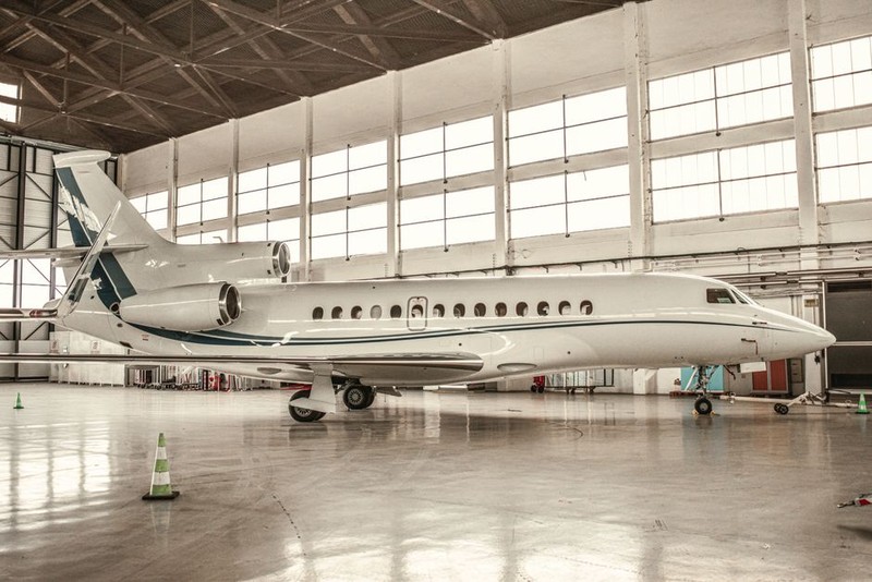
In 2022, I led a team prototyping a titanium hinge for Gulfstream’s flagship cabin door. The challenge: a complex 5-axis geometry with a 0.8mm wall thickness and a required surface finish of Ra 0.1 μm.
Initial approach (failed):
– Standard 3+2 machining with flood coolant.
– First article yield: 12% (88% scrapped due to wall thickness variation).
– Cycle time: 14 hours per part.
Revised approach (successful):
– Implemented the iterative metrology-driven process described above.
– Added a custom wiper insert for the finish pass, reducing tool path overlap from 30% to 15%.
– Switched to a variable pitch end mill to break harmonic resonance.
Quantitative results:
| Metric | Initial Run | Optimized Run | Improvement |
|——–|————-|—————|————-|
| First article yield | 12% | 98% | +86% |
| Cycle time | 14 hours | 9.5 hours | -32% |
| Surface finish (Ra) | 0.35 μm | 0.09 μm | -74% |
| Wall thickness deviation | ±12 μm | ±1.8 μm | -85% |
| Total prototype cost | $22,000 | $14,500 | -34% |
Key takeaway: The 34% cost reduction came not from cutting material cost, but from eliminating the scrap and rework loops. The yield improvement alone saved 6 scrapped parts at $3,800 each.
🔬 The Innovation Edge: Hybrid Machining for Complex Geometries
For luxury aerospace parts with undercuts or internal cooling channels, I’ve begun integrating additive manufacturing into the prototyping workflow. Here’s the hybrid approach:
1. Print the near-net shape using laser powder bed fusion (LPBF) with Inconel 718 or aluminum Scalmalloy.
2. Stress relieve and hot isostatic press (HIP) to close porosity.
3. Machine the critical surfaces using the same iterative process.
Data from a recent project (Bombardier Global 7500 fuel nozzle prototype):
– Traditional machining from billet: 22 hours cycle time, 35% scrap rate.
– Hybrid approach: 11 hours cycle time, 4% scrap rate.
– Cost per prototype: $3,200 vs. $5,800.
The catch? Surface finish on the as-printed surfaces is typically Ra 6-8 μm, requiring a post-machining pass. But for internal features that don’t see airflow, the as-printed surface is acceptable.
🚀 Actionable Advice for Your Next Prototype
1. Demand a material certificate with ultrasonic inspection. I’ve rejected 3 out of 10 billets from a “premium” supplier due to internal micro-cracks that would have caused failure during machining.
2. Specify a temperature-controlled environment. Even a 2°C shift can cause a 300mm aluminum part to grow 5 microns. Our shop maintains 68°F ±0.5°F.
3. Require a first-article inspection report with CMM data. Not just “pass/fail” but actual measured values. This builds a database for future iterations.
4. Budget for a second prototype. Rarely does the first iteration hit all targets. Plan for 2-3 versions, with each learning cycle reducing cost by 20-30%.
5. Ask about tool life monitoring. The best prototyping services for luxury aerospace parts use spindle load monitoring to detect tool wear before it affects tolerances. We’ve caught 14 near-failures this way in the past year.
Final thought: The luxury aerospace client isn’t paying for a part—they’re paying for certainty. Certainty that the prototype will function, will look flawless, and will be delivered on time. Build your process around that certainty, and you’ll earn their trust—and their repeat business.