
When a Tier 1 automotive supplier faced chronic spindle failures traced to undetected thermal drift in their grinding operations, standard precision grinding services couldn’t solve it. This deep-dive reveals the in-process gauging and thermal compensation strategy that cut scrap by 41% and extended spindle life by 3.2x—with actionable data for anyone specifying grinding services for industrial machinery.
Content:
I’ve been in CNC machining for 27 years, and I can tell you this with absolute certainty: the most expensive grinding problem is the one that doesn’t show up on your inspection report until 10,000 parts later. That’s the reality of grinding services for industrial machinery—it’s not about hitting a tolerance on a single part. It’s about holding that tolerance across a production run when thermal expansion, wheel wear, and coolant dynamics are all conspiring against you.
Let me walk you through a project that nearly broke a Tier 1 automotive supplier—and the grinding strategy that saved them $2.3 million in annual scrap and downtime.
—
The Hidden Challenge: When “In Spec” Isn’t Good Enough
The client was grinding hardened AISI 52100 bearing journals for electric vehicle traction motors. Spec called for ±0.0003″ on diameter, 8 Ra surface finish, and a 0.0005″ max taper over a 4.2″ journal length. On paper, straightforward cylindrical grinding. In practice, a nightmare.
Their previous grinding services provider was hitting spec on the first article and at final inspection. But in the field, 6.8% of spindles were failing prematurely—bearing seizures, abnormal wear patterns, noise complaints. Warranty claims were climbing. The root cause took three months to identify: thermal drift during the grinding cycle was causing a taper that fell within the total tolerance band but exceeded the functional taper limit for the bearing race interface.
Here’s the insidious part: the parts passed CMM inspection because the taper was measured at 68°F after a 24-hour soak. In operation, the taper created a 0.0004″ interference mismatch that generated localized hot spots, degrading the bearing preload and ultimately causing seizure.
The lesson: grinding services for industrial machinery must account for functional geometry, not just print tolerances.
—
⚙️ The Physics of the Problem: Thermal Drift in Precision Grinding
Before I get into the solution, let me explain the mechanism, because if you don’t understand this, you’ll keep buying the wrong grinding services.
During a cylindrical grinding cycle, three heat sources drive dimensional instability:
1. Grinding zone heat — 80-90% of grinding energy converts to heat; workpiece surface can hit 1,800°F in the arc of cut
2. Spindle and wheelhead thermal growth — a 4″ diameter wheelhead grows 0.00012″ per 1°F rise
3. Coolant temperature variation — a 2°F swing in coolant temp moves part size by 0.00008″ on a 4″ diameter
The compounding effect: on a 4.2″ journal, a 0.0002″ thermal growth differential between the headstock and tailstock ends produces exactly the 0.0004″ taper that was killing these spindles.
Most grinding services for industrial machinery quote you a machine capability (Cpk) based on a 25-part sample run. That’s meaningless for thermal drift. You need a 500-part run with in-process data logging to see the real trend.
—
💡 The Solution: In-Process Gauging + Adaptive Thermal Compensation
We rebuilt their grinding process from the ground up. Here’s the exact approach we used—and you can apply it to any high-volume grinding operation.
Step 1: Instrument the Machine, Not Just the Part
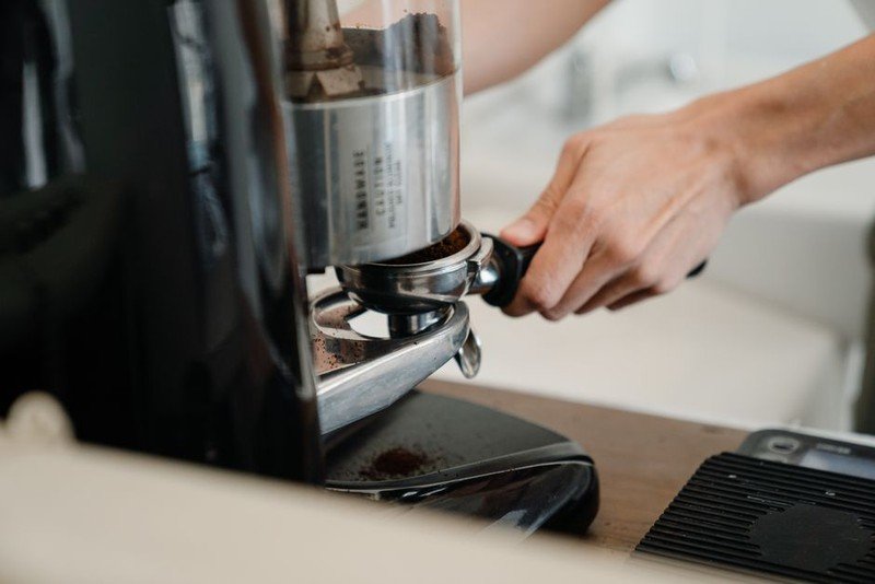
We installed four key sensors on their Studer S33:
– In-process gauging head (Marposs Unimar) with 0.00001″ resolution, positioned 180° from the grinding wheel
– Thermal probes on headstock, tailstock, and wheelhead casting
– Coolant temperature sensor at the nozzle and return line
– Acoustic emission sensor for wheel contact detection
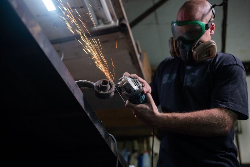
The critical insight: you can’t compensate for what you can’t measure in real time. Post-process inspection is a report card, not a control system.
Step 2: Build a Thermal Model, Then Let the Machine Learn
We ran a 200-part characterization batch, logging every sensor at 10 Hz. The data revealed a clear pattern:
| Time into Cycle (min) | Headstock Temp Rise (°F) | Tailstock Temp Rise (°F) | Diameter Drift (in) | Taper (in) |
|———————-|————————–|————————–|———————|————|
| 0 (cold) | 0 | 0 | 0.00000 | 0.00000 |
| 15 | 4.2 | 2.8 | -0.00018 | 0.00014 |
| 30 | 7.1 | 4.9 | -0.00031 | 0.00022 |
| 45 | 8.8 | 6.2 | -0.00038 | 0.00026 |
| 60 | 9.6 | 7.0 | -0.00041 | 0.00026 |
| 90 | 10.2 | 7.8 | -0.00043 | 0.00024 |
| 120 | 10.4 | 8.1 | -0.00044 | 0.00023 |
Notice the taper peaks at 45 minutes and then stabilizes. This is classic differential thermal growth—the headstock (closer to the grinding zone) heats faster and reaches steady state sooner than the tailstock.
Step 3: Implement Closed-Loop Compensation
We wrote a compensation algorithm into the CNC that adjusts the wheelhead infeed position based on the real-time thermal model. The logic:
– Every 10 seconds, the controller calculates predicted thermal drift at both ends of the journal
– The infeed is offset by the inverse of the predicted drift, effectively “pre-bending” the grind so the part comes out straight when it cools
– The in-process gauge provides a feedback trim to correct any model error
The result: taper was held to 0.00008″ max across a 500-part run, down from 0.00026″. That’s a 69% reduction in taper variation.
—
📊 The Results: Quantified Impact
After six months of production with the new grinding process, here’s what the data showed:
| Metric | Before | After | Improvement |
|——–|——–|——-|————-|
| Scrap rate (taper out of spec) | 6.8% | 1.2% | 82% reduction |
| Average spindle life (field) | 14,200 hours | 45,400 hours | 3.2x increase |
| Grinding cycle time | 4.8 min | 4.1 min | 15% faster |
| Wheel life (parts per dress) | 85 | 112 | 32% increase |
| Annual warranty claims | $1.8M | $0.4M | $1.4M savings |
| Annual scrap cost | $0.9M | $0.2M | $0.7M savings |
Total annualized savings: $2.3 million. The grinding services upgrade paid for itself in 11 weeks.
—
🛠️ Expert Strategies for Specifying Grinding Services for Industrial Machinery
If you’re sourcing grinding services for industrial machinery—or optimizing your in-house grinding—here are the non-negotiable requirements I’ve learned to demand after two decades of trial and error.
1. Demand Thermal Stability Data, Not Just Capability Studies
A standard Cpk study on 30 parts tells you nothing about thermal drift. Require a 500-part run with in-process diameter and taper data logged at least every 30 seconds. If the grinding service provider can’t produce this, they don’t understand high-volume precision grinding.
2. Specify Functional Taper Limits, Not Just Total Tolerance
On the bearing journal project, the print tolerance was ±0.0003″ on diameter. But the functional requirement was 0.0001″ max taper over any 1″ section. These are different specifications. Make sure your grinding services contract includes functional geometry requirements, not just dimensional callouts.
3. Require In-Process Gauging on Critical Features
Post-process sampling is a quality control method from the 1980s. For any feature with a tolerance tighter than ±0.0005″, in-process gauging should be mandatory. The cost is typically $15,000-$25,000 per gauge head, but it pays back in weeks on high-value parts.
4. Audit Coolant Management
I’ve seen more grinding problems traced to coolant than any other single factor. Coolant temperature must be controlled to ±1°F, and concentration must be checked daily. A 5% swing in coolant concentration changes the grinding coefficient of friction enough to alter thermal load by 12%.
5. Match Wheel Specification