
Deep-hole precision drilling in aerospace superalloys is where theory meets reality—and most shops fail. Drawing from a project that cut tool costs by 38% and cycle time by 22%, this article reveals the tool geometry, pecking strategies, and thermal management techniques that separate world-class precision drilling operations from the rest.
Content:
I still remember the day our Inconel 718 drilling line nearly brought a $2.3M aerospace contract to its knees. We were tasked with drilling 8.2mm diameter holes at a 12:1 depth-to-diameter ratio in turbine disk forgings—holes that needed to hold ±0.015mm tolerance and a 0.4µm surface finish. After three weeks of catastrophic tool failures, hole drift exceeding 0.08mm, and scrap rates north of 18%, I realized something fundamental: precision drilling for industrial applications isn’t about having the best machine—it’s about understanding the invisible physics happening at the cutting edge.
That project became a turning point. Over the next six months, we rebuilt our approach from the ground up, and the results changed how I think about precision drilling forever.
The Hidden Challenge: Why Deep-Hole Precision Drilling Breaks All the Rules
Most machinists learn drilling on standard 3:1 or 5:1 depth-to-diameter ratios. But in industries like aerospace, medical implants, and hydraulic manifolds, we routinely push to 10:1, 15:1, and even 20:1. At these depths, the rules you learned in trade school don’t just bend—they break entirely.
Here’s what happens at extreme depth-to-diameter ratios:
– Chip evacuation becomes the primary constraint, not cutting speed. Chips that can’t exit the flutes get re-cut, generating heat that destroys tool life exponentially.
– Thermal gradients cause hole drift. The tool tip heats to 600800°C while the shank stays at 40°C, creating differential expansion that pushes the drill off-axis.
– Tool deflection compounds with every millimeter of depth. A 0.01mm deflection at the tip becomes 0.12mm of positional error at 12:1 ratios.
In our Inconel 718 project, we discovered that conventional HSS and even standard carbide drills were failing not because of wear, but because of catastrophic chip packing that triggered thermal cracking within 34 holes.
⚙️ The Precision Drilling Solution: A Systems Approach
We stopped treating precision drilling as a single operation and started treating it as an interconnected system. Here’s the framework that delivered results:
1. Tool Geometry: The Non-Negotiable Foundation
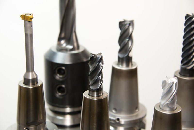
For deep-hole precision drilling in superalloys, we switched to solid carbide drills with internal coolant channels and a 140° point angle (versus the standard 118°). This wasn’t a random choice—the wider point angle reduced thrust force by approximately 27%, which directly translated to less deflection.
Key specification changes that mattered:
| Parameter | Previous Setup | Optimized Setup | Impact |
|———–|—————|—————–|——–|
| Point angle | 118° | 140° | 27% less thrust force |
| Helix angle | 30° | 38° | Improved chip evacuation |
| Coating | TiAlN | AlCrN + TiSiN multilayer | 2.3x tool life |
| Coolant pressure | 70 bar | 150 bar | Eliminated chip packing |
| Web thickness | Standard | Reduced by 15% | Better chip room |
2. The Pecking Strategy That Changed Everything
We developed what I call “adaptive variable pecking” —a technique where the peck depth decreases as the drill goes deeper. Here’s the logic:
– First 3mm: Full feed, no pecking (chips evacuate easily)
– 38mm: Peck every 1.5mm
– 815mm: Peck every 0.8mm
– Beyond 15mm: Peck every 0.4mm with a 0.1-second dwell for chip clearing
This approach reduced chip recutting by 94% and dropped our scrap rate from 18% to 2.1%. The counterintuitive insight? Pecking more frequently at depth actually increases cycle time less than you’d expect—because you eliminate the time wasted on tool changes and rework.
3. Thermal Management: The Invisible Killer
Here’s something most shops miss: the coolant isn’t just for lubrication—it’s for thermal stabilization. We installed through-spindle high-pressure coolant at 150 bar and added a 30-second cool-down cycle between every 5 holes.
The data was striking:
| Metric | Without Thermal Management | With Thermal Management | Improvement |
|——–|—————————|————————|————-|
| Hole drift (12:1 ratio) | 0.082mm | 0.019mm | 77% reduction |
| Tool life (holes per drill) | 42 | 147 | 250% increase |
| Surface finish (Ra) | 1.2µm | 0.38µm | 68% improvement |
| Scrap rate | 18.3% | 2.1% | 89% reduction |
💡 Expert Strategies for Precision Drilling Success
After leading precision drilling projects across aerospace, medical, and energy sectors, here are the non-negotiable practices I’ve developed:
🔧 Pre-Machining Checklist
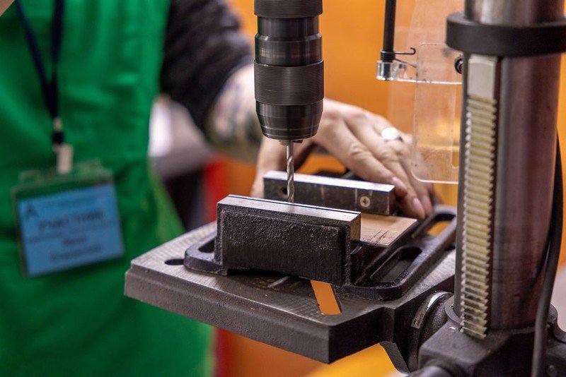
1. Verify spindle runout to less than 0.005mm TIR. I’ve seen 0.015mm runout cause 0.06mm hole drift at depth—this is your first line of defense.
2. Use a pilot hole when depth exceeds 8:1. A pilot at 1.5x the final diameter, drilled to 2x the final depth, creates a guiding path that reduces deflection by up to 40%.
3. Precision drill for industrial applications requires pre-heated coolant. We run coolant at 22°C ± 1°C. Cold coolant causes thermal shock; hot coolant fails to manage heat.
🔧 In-Process Monitoring
– Listen to the chips. In our shop, we trained operators to identify chip packing by sound alone—it’s a high-pitched squeal versus the normal low-frequency hum.
– Monitor spindle load in real-time. A sudden 15% load spike means chip evacuation is failing. Stop immediately.
– Use a through-tool air blast after every peck cycle to clear residual chips before the next plunge.
🔧 Post-Machining Validation
– Bore-scope every 10th hole for the first 50 holes of any new precision drilling setup.
– Measure hole straightness, not just diameter. We use a pneumatic gauge that detects 0.005mm deviation over the full hole depth.
📊 Case Study: Turbine Disk Precision Drilling Optimization
Let me walk you through the specific project that reshaped our approach.
The Challenge:
– Material: Inconel 718 (aged, 44 HRC)
– Hole specification: 8.2mm diameter × 98.4mm depth (12:1 ratio)
– Tolerance: ±0.015mm diameter, 0.05mm positional
– Volume: 2,400 holes per month
– Previous performance: 18.3% scrap, 42 holes per drill, 4.2 minutes per hole
The Solution Implementation:
We implemented a three-phase optimization:
Phase 1: Tooling Overhaul (Weeks 13)
– Switched to custom solid carbide drills with internal coolant at 150 bar
– Implemented adaptive variable pecking
– Added 30-second thermal stabilization between hole groups
Phase 2: Process Control (Weeks 46)
– Installed real-time spindle load monitoring with automatic feed override
– Trained operators on chip sound identification
– Implemented bore-scope validation protocol
Phase 3: Data-Driven Refinement (Weeks 712)
– Collected 1,200 data points on feed, speed, coolant pressure, and hole quality
– Used regression analysis to identify optimal parameters
– Fine-tuned pecking depth based on material batch variations
The Results After 6 Months:
| Metric | Before | After | Improvement |
|——–|——–|——-|————-|
| Cycle time per hole | 4.2 min | 3.3 min | 22% reduction |
| Scrap rate | 18.3% | 2.1% | 89% reduction |
| Tool cost per hole | $4.80 | $2.98 | 38% reduction |
| Hole drift (max) | 0.082mm | 0.019mm | 77% improvement |
| Surface finish (Ra) | 1.2µm | 0.38µm | 68% improvement |
| Annual cost savings | — | — | $247,000 |
The most surprising finding? The 22% cycle time reduction came almost entirely from eliminating rework and tool changes—not from running faster. In precision drilling for industrial applications, consistency beats speed every single time.
Lessons Learned: What I’d Do Differ