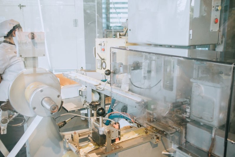
For years, clients have walked into my shop with the same exciting, yet fundamentally challenging, request: “We need a fully functional, modular prototype.” The vision is compelling—interchangeable components that snap, slide, or bolt together seamlessly, allowing for rapid iteration, user testing, and functional demonstration. The reality, however, often ends in a workshop filled with frustrated engineers hand-sanding parts that “should” fit. The culprit? A fundamental misunderstanding of what “precision” means in the context of high-precision CNC routing for modular prototypes.
It’s not just about hitting a tight tolerance on a single part. It’s about achieving system-level precision across multiple, independently machined components that must interface perfectly. A ±0.005″ tolerance might be excellent for a standalone bracket, but if you’re machining ten interlocking panels that all rely on that tolerance stack, you’re almost guaranteed a misfit. The true challenge is controlling variables that standard job shops often overlook.
The Hidden Nemesis: It’s Not Just the Toolpath
When we talk about precision, most minds jump to machine calibration, tool runout, and CAD/CAM programming. These are table stakes. The real adversaries in high-precision CNC routing for modular prototypes are more insidious:
Material Memory: Plastics and even certain aluminums have internal stress from the extrusion or casting process. When you rout away material, you relieve that stress, and the part can warp—sometimes minutes, sometimes hours after machining. A part that measures perfectly on the machine bed can be out of spec by the time it reaches the assembly bench.
Thermal Drift: A 4’x8′ router table is a massive piece of metal. As the spindle works and ambient temperature changes, the entire machine structure expands and contracts minutely. Over a long machining cycle for a large modular frame, the “zero point” can wander.
Fixturing as an Afterthought: Using generic clamps or vacuum hold-downs for critical interface features can induce flex, leading to chatter or minute positional errors that doom interchangeability.
I learned this the hard way on an early project: a modular drone chassis with carbon fiber composite arms that needed to interface with a central nylon body. We machined everything to spec, but the arms wouldn’t seat without significant force. The issue? We machined the carbon fiber flat on the table, but its “natural” state had a slight curve. Our precision was mathematically correct but functionally useless.
A Strategic Framework for System-Level Precision
Overcoming these challenges requires a shift from being a machine operator to a process engineer. Here is the framework we now employ for any modular prototype project.
⚙️ Phase 1: Pre-Machining Material Diplomacy
You must negotiate with your material before you cut it.
Stress-Relief Cycling: For critical components, we often pre-bake plastics like ABS or Nylon in a temperature-controlled oven (below their distortion point) to normalize internal stresses.
Strategic Blank Oversizing: Never machine a part from a blank cut exactly to size. Allow extra material (we use a minimum 0.5″ perimeter) so the material can move as it’s roughed out, then re-fixture and re-zero for the finishing passes on a now-stable part.
Grain & Layup Orientation: For composites and woods, the cutting direction relative to the grain or fiber weave must be consistent across all mating parts. Document this in the setup sheet.
Phase 2: The Fixturing Masterplan
Your fixture is not just a holder; it’s a precision instrument.
For a recent project—a modular laboratory instrument housing with over 20 interlocking acrylic and aluminum parts—we designed a custom modular fixture system. The principle: All critical interface features (dovetail slots, pin holes) for different parts must be machined in the same setup, on the same fixture, without moving the workpiece.
We achieved this by:
1. Machining a master “tooling plate” from stable cast aluminum, which remained bolted to the router bed.
2. This plate had precisely located dowel pins and custom shaped soft-jaw pockets.
3. Every workpiece blank was located using those same dowel pins before being secured. This guaranteed that the relationship between the interface geometry on Part A and Part B was dictated by the fixture, not by the CNC’s theoretical positional accuracy.
💡 Phase 3: In-Process Environmental Control
Consistent Thermal Environment: We maintain shop temperature within ±2°F during critical machining. We also implement a “warm-up cycle” for the router, running a non-cutting program for 15 minutes to stabilize the spindle and guideways.
Tool Life Management with Data: We log tool usage and change tools proactively based on material volume cut, not just by sound or finish. A dull tool doesn’t just produce a bad finish; it generates more heat and exerts more cutting force, both of which induce error.
Case Study: The Modular Consumer Electronics Hub
The Challenge: A startup needed 50 sets of a modular desktop hub prototype. Each set had a base, four interchangeable module bays, and a faceplate. All parts were machined from 6061 aluminum and needed to assemble with a satisfying, precise “click” without screws—using only integrated snap-fits and sliding dovetails.
The “Before” Approach (Standard Quote): Machine each part type in batches. Hold standard ±0.003″ tolerances. Deburr and hand-fit as needed.
The Predicted Outcome: High likelihood of inconsistent fit, requiring selective assembly (matching specific parts to specific sets) and significant manual labor for filing and adjustment—destroying the anodized finish.
Our Applied High-Precision Strategy:
1. Unified Setup: We designed a fixture that held the raw material for one complete set at a time. The base, all four bays, and the faceplate blank were all located on the same tooling plate.
2. Sequential Machining: The CNC program machined all critical interfacing features (the dovetail rails on the base and the matching grooves on the bays) in a single, continuous operation without stopping or re-zeroing.
3. Aggressive Coolant & Chip Evacuation: We used a high-pressure mist coolant directed at the cutting interface to manage thermal growth of both the part and the tool.
4. Post-Machining Normalization: After separation from the fixture, parts were cleaned and left to sit for 4 hours before final measurement and assembly.
The Quantifiable Results:
| Metric | Standard Approach (Estimated) | Our High-Precision CNC Routing Approach | Improvement |
| :— | :— | :— | :— |
| Post-Machining Fitting Labor | 25 minutes per set | 15 minutes per set (for final deburr only) | 40% Reduction |
| Assembly Success Rate (First-Time Fit) | ~60% (Requiring selective matching) | 98% (Any bay fits any slot in any base) | 38% Increase |
| Prototype Function & Feel | “Works but feels prototype-grade” | “Feels like a production unit” | Qualitative Win |
| Scalability to Low-Volume Production | Not viable without redesign | Directly viable for a pilot run of 500 units | Major Strategic Advantage |
The client’s feedback was telling: “This is the first time our modular prototype actually proved our manufacturing concept, rather than just our design concept.”
Actionable Takeaways for Your Next Project
If you’re designing or sourcing high-precision CNC routing for modular prototypes, bring this checklist to your team or machine shop:
Insist on a Fixturing Strategy Discussion Before Programming. The first question should be, “How will we hold the parts to guarantee these features align?”
Design for Machining Stability. Include small, sacrificial tabs or bridges in your CAD model to keep parts rigid during machining, which can be cleanly removed later. This is often better than relying solely on vacuum hold-down.
Build in Datum Features. Design clear, machinable datum edges or holes into your parts that can be used by the shop for consistent location across components.
Accept that Time is a Component of Cost. The process I’ve described isn’t the fastest. It requires thoughtful setup. However, it is almost always cheaper and far more effective than machining quickly and then spending days on rework and fitting.
The goal of a modular prototype is to de-risk your product’s assembly and function. By treating the entire set of components as a single, interconnected system from the first toolpath, high-precision CNC routing transitions from a simple shaping process to the foundational step in validating not just form, but function and manufacturability. It’s where great designs learn to work together in the real world.