🔧 Challenges in CNC Milling Radius Programming
Creating precise radius cuts in CNC milling requires careful programming to avoid errors that lead to scrap parts, tool damage, or inefficient machining. Let’s explore the most common hurdles manufacturers face:
1. Tool Deflection & Chatter
- Issue: Small-radius cuts or deep pockets increase tool pressure, causing deflection and vibration.
- Impact: Poor surface finish, dimensional inaccuracies, and shortened tool life.
2. Incorrect G-Code for Complex Radii
- Issue: Manual G-code programming for arcs (G02/G03) often leads to syntax errors or incorrect I/J/K values.
- Example: A misplaced I-value in a circular interpolation can create an oval instead of a perfect radius.
3. Material-Specific Complications
- Hardened steels demand slower feed rates, while softer metals (like aluminum) risk burring if speeds are too high.
4. Machine & Controller Limitations
– Older CNC controllers may struggle with high-precision radius calculations, leading to jerky movements or approximation errors.
✅ Solutions & Best Practices for Flawless Radius Milling
1. Optimize Toolpaths for Smooth Radii
- Use climb milling for better surface finish and reduced tool stress.
- Implement trochoidal milling for tight radii to minimize heat buildup.
2. Accurate G-Code Programming
Here’s a correct CNC milling radius program example for a 10mm radius arc (clockwise):
G01 X0 Y0 F100 (Start at origin)
G02 X10 Y0 I5 J0 (Arc to X10, radius 5mm)
- Key Detail: The I value is the incremental distance from the start point to the arc’s center (5mm in this case).
3. Adaptive Toolpath Strategies
- High-speed machining (HSM): Maintains constant tool engagement for smoother radius cuts.
- Dynamic milling: Reduces radial depth of cut to prevent deflection.
4. Material-Specific Adjustments
| Material | Recommended Feed Rate | Spindle Speed |
|---|---|---|
| Aluminum | 0.1–0.3 mm/tooth | 10,000–20,000 RPM |
| Steel | 0.05–0.15 mm/tooth | 1,500–3,500 RPM |
| Titanium | 0.04–0.1 mm/tooth | 800–1,500 RPM |
📊 Real-World CNC Milling Radius Program Examples
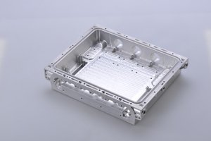
Case 1: Internal Pocket with Rounded Corners
Challenge: Machining a 20mm pocket with 5mm corner radii in stainless steel.
Solution:
1. Tool: 6mm carbide end mill.
2. Code Snippet:
G01 X5 Y5 F200

   G02 X15 Y5 I5 J0 (First radius)

   G01 X20 Y10

   G02 X20 Y20 I0 J5 (Second radius)
Case 2: 3D Contoured Radius
Challenge: Smoothly milling a hemispherical mold cavity.
Solution:
– Use CAM software (e.g., Fusion 360, Mastercam) to generate 3D toolpaths.
– Employ ball-nose end mills for uniform surface finish.
🔧 Pro Tips for Error-Free Radius Milling
- Verify programs with simulation software before machining.
- Use cutter compensation (G41/G42) to adjust for tool wear.
- Lubricate aggressively when cutting tough materials to avoid heat distortion.
Final Thoughts
Mastering CNC milling radius programming isn’t just about correct G-code—it’s about understanding tool behavior, material response, and machine capabilities. By applying these practical examples and best practices, manufacturers can achieve tighter tolerances, longer tool life, and faster production cycles.
Need expert support? Our team specializes in CNC optimization—reach out for tailored solutions!