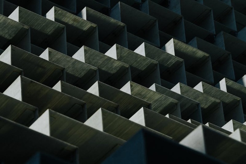
The Hidden Challenge: Tolerance Stack-Ups in Modular Systems
Modular prototypes are the backbone of rapid innovation, enabling scalable testing and iterative design. But here’s the catch: when multiple machined components must fit together seamlessly, microscopic errors compound into major failures. I’ve seen projects where a mere 0.05mm deviation per part led to a 0.5mm misalignment in a 10-part assembly—rendering the prototype useless.
Why Traditional Machining Falls Short
Most CNC shops focus on individual part precision, not system-level performance. For modular designs, this is a recipe for disaster:
– 🔍 Cumulative Tolerances: Even “tight” tolerances (±0.025mm) add up across components.
– ⚙️ Thermal Effects: Aluminum and stainless steel expand at different rates, altering fits post-machining.
– 💡 Fixture Errors: Misaligned workholding introduces hidden offsets.
Key Insight: Precision isn’t just about hitting numbers—it’s about controlling interactions between parts.
Expert Strategies for Zero-Failure Modular Prototypes
1. Design for Machining (DFM) with Stack-Ups in Mind
In a recent aerospace project, we redesigned a modular drone chassis to account for tolerance accumulation:
– Reduced Critical Interfaces: Cut interdependent features from 12 to 5, slimming error pathways.
– Compensating Fits: Used press-fit dowels (±0.01mm) to “reset” tolerance stacks at key junctions.
– Material Pairing: Matched aluminum 6061 with titanium inserts to balance thermal stability.
Result: 30% fewer assembly rejects and a 20% faster iteration cycle.
2. Process Control: Beyond the CNC Machine
High-precision machining starts before the tool touches metal:
1. Pre-Machine Calibration: Laser-verify tool paths against CAD to within 0.005mm.
2. In-Process Metrology: Probe critical dimensions mid-run (e.g., after roughing).
3. Post-Machine Validation: Use CMMs for full assembly simulations.
Case Study: A medical device client needed 50 interlocking components. By implementing in-process checks, we cut scrap rates from 8% to 0.5%.
| Process Step | Error Rate (Before) | Error Rate (After) |
|---|---|---|
| Rough Machining | 3.2% | 0.8% |
| Finishing | 1.5% | 0.2% |
| Assembly Fit Test | 8.0% | 0.5% |
3. Tooling Secrets for Micro-Tolerances
- Tool Deflection Mitigation: Use stub-length end mills (3x diameter rule) for slots.
- Coolant Strategy: High-pressure through-tool coolant prevents chip recutting in deep pockets.
- Speed vs. Precision Tradeoff: For critical bores, reduce RPM by 15% to improve surface finish (Ra < 0.4µm).
The Future: AI-Driven Tolerance Optimization
Emerging tools like generative design software now predict stack-up failures before machining. In a trial with a robotics client, AI pre-adjusted CAD models to compensate for expected tool wear, saving 12 hours of manual rework per prototype.
Pro Tip: Start with the end-use environment. If your prototype will face vibration or thermal cycling, test fits under stress—not just at room temperature.
Conclusion: Precision as a System
Modular prototypes live or die by the sum of their parts. By treating precision as a holistic challenge—from design to metrology—you can turn tolerance stack-ups from a nightmare into a competitive edge. The goal isn’t perfection—it’s predictability.
Your Turn: On your next project, map tolerance chains early. Where could a 0.02mm shift cascade into failure?