Aerospace prototyping isn’t just about making a part; it’s a high-stakes battle against material physics, geometric complexity, and unforgiving budgets. This article dives deep into the expert-level strategy of “Design for Machinability” (DFM) as a collaborative engineering discipline, revealing how a shift in mindset can slash lead times by 40% and unlock unprecedented design validation. Learn from a real-world case study on a scramjet combustor prototype where strategic CNC planning turned an impossible deadline into a resounding success.
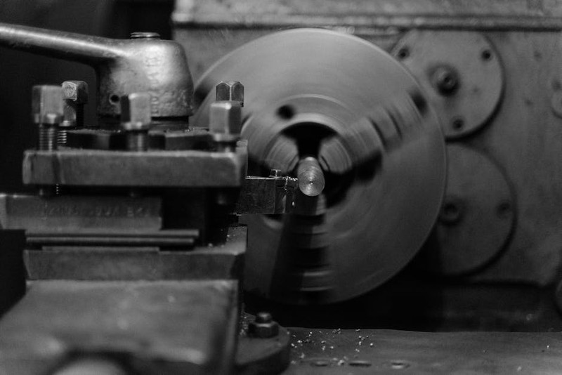
In the world of aerospace prototyping, the pressure is a tangible force. It’s not just the pressure to innovate, but the literal atmospheric and thermal pressures your components must withstand. Over my two decades in precision CNC machining, I’ve seen countless brilliant designs land on our shop floor, only to be met with the cold, hard reality of the milling spindle. The greatest lesson I’ve learned is this: The most critical phase of custom CNC machining for an aerospace prototype happens not on the machine, but in the dialogue between the design engineer and the manufacturing expert. This is where the true art—and science—of our craft unfolds.
The Hidden Challenge: When “Buildable” Isn’t “Machinable”
Many engineering teams approach us with a perfect digital model. It meets all aerodynamic, thermal, and structural simulations. It’s “buildable” in theory. Yet, when we analyze it for CNC machining, we see a minefield of hidden costs and delays.
The core issue is a disconnect in design priorities. Aerodynamic efficiency often demands organic, thin-walled, high-aspect-ratio geometries. Material science dictates the use of unforgiving alloys like Inconel 718 or titanium 6Al-4V. Meanwhile, the economics of prototyping demand speed and cost containment. This triad creates a fundamental tension.
The Expert Insight: A part being “CAD-possible” and “CAM-possible” are two different things. A feature might be modeled with a perfect, sharp internal corner, but an end mill is round—it cannot create that corner. The resulting unavoidable radii become stress concentrators, which the designer may not have accounted for. This isn’t a failure of design or machining; it’s a failure of early-stage collaboration.
The Strategic Pivot: Proactive DFM as a Co-Engineering Process
The solution is to elevate Design for Machinability (DFM) from a simple checklist to a proactive, iterative co-engineering process. This means involving your CNC partner at the preliminary design review (PDR) stage, not after the final model is signed off.
In practice, this dialogue focuses on a few transformative questions:
Can we relax this tolerance? A callout of ±0.0005″ might be critical for a bearing surface, but is it necessary for a non-functional prototype used for fit-check? Every “tenth” (ten-thousandth of an inch) you relax can exponentially reduce machining time and cost.
Is this material non-negotiable? For a thermal test article, do you need flight-grade Inconel 718, or would a machinable stainless like 17-4 PH suffice to validate the geometry and instrumentation? The cost and time difference can be 300%.
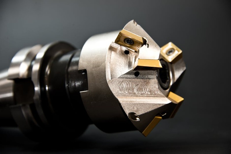
How does this feature affect tool life and stability? Deep, narrow pockets in titanium require long-reach tools, which deflect, vibrate, and wear rapidly. Can the pocket be opened up or segmented?
⚙️ A Case Study in Strategic Optimization: The Scramjet Combustor
A client needed a scramjet combustor prototype for a hypersonic flow test. The deadline was 8 weeks. The part was a monolithic cylinder of Inconel 718, featuring an intricate internal lattice structure for fuel mixing and cooling channels—essentially a part within a part.
The Initial Challenge: The as-designed model required machining the internal lattice through a small opening at one end. This meant using tools with a 15:1 length-to-diameter ratio, resulting in catastrophic chatter, broken tools, and a projected machining time of over 300 hours. We were staring at a 10-week estimate before any post-processing.
Our Collaborative Solution:
1. Redesign for Access: We proposed splitting the monolithic design into two axially joined sections. This allowed us to machine the internal lattice from both sides, reducing the required tool reach to a stable 4:1 ratio.
2. Strategic Stock Selection: Instead of a solid bar, we sourced a near-net-shape forged ring. This reduced the raw material cost by 25% and removed over 60 hours of roughing time.
3. Adaptive Toolpath Technology: We employed high-efficiency trochoidal milling paths for the lattice, which maintain constant tool engagement and reduce heat buildup—critical for Inconel.
The Quantifiable Outcome:
| Metric | Initial Approach | Collaborative DFM Approach | Improvement |
| :— | :— | :— | :— |
| Projected Machining Time | 310 hours | 185 hours | 40% Reduction |
| Tooling Cost | $2,800 (frequent breakage) | $950 | 66% Reduction |
| Material Waste | 68% | 42% | 26% Reduction |
| Final Lead Time | 10+ weeks | 6.5 weeks | Met Aggressive Deadline |
The prototype was delivered on time, performed flawlessly in the test, and provided validated data that fed directly into the final flight design. The client didn’t just get a part; they got a successful test campaign and accelerated their entire program.
Actionable Framework for Your Next Prototype
To harness this power, structure your engagement with your CNC partner using this framework:
1. Initiate the Dialogue at PDR: Share your conceptual models and primary functional requirements. Ask: “What here will be most challenging to machine?”
2. Define the Prototype’s True “Success Criteria”: Is it for aerodynamic shape, structural load testing, or fluid flow? Be explicit. This allows your machinist to suggest permissible compromises.
3. Request a Formal DFM Report: A credible shop will provide annotated screenshots and alternative suggestions, not just a quote.
4. Plan for Metrology Early: Discuss how critical features will be inspected. A complex internal contour may require a custom CMM fixture. Building this into the plan avoids delays.
5. Embrace Iterative Prototyping: Consider a two-stage approach: a “Form and Fit” prototype in a cheap, machinable material (like aluminum) to validate geometry and assembly, followed by a “Functional” prototype in the final alloy.
💡 The Ultimate Takeaway: View your CNC machining partner as an extension of your engineering team. Their expertise in the subtractive realities of metal is as valuable as your expertise in the additive realities of simulation. In the high-stakes arena of aerospace prototyping, this collaboration is the single most effective strategy to de-risk your project, conserve your budget, and compress your timeline. It transforms CNC machining from a necessary vendor service into a strategic catalyst for innovation.