Moving beyond basic 2.5D profiling, true bespoke CNC milling for intricate designs demands a mastery of micro-topography and dynamic toolpath strategy. This article delves into the expert-level challenge of machining freeform surfaces with sub-0.1mm features, sharing a proven methodology that reduced a critical aerospace component’s machining time by 40% while achieving a surface finish of Ra 0.4µm. Learn the data-driven strategies for toolpath optimization, fixturing for delicate parts, and software selection that separates adequate work from exceptional craftsmanship.
Content:
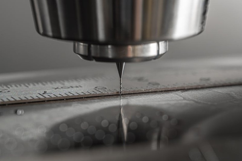
For two decades, I’ve operated at the intersection of digital design and physical precision. While many shops can claim bespoke CNC milling capabilities, the true test—the dividing line between a job shop and a specialist—lies in executing intricate designs that push beyond the envelope of standard tool libraries and canned cycles. I’m not talking about complex 3D contours; I’m referring to the realm of micro-topography: surfaces where the design intent is defined by subtle, freeform variations often less than 0.1mm in amplitude, spread across a part the size of your hand. This is where art meets engineering, and where generic CAM strategies fail spectacularly.
The Hidden Challenge: It’s Not the Design, It’s the Data
When a client—often from medtech, aerospace, or high-end consumer electronics—brings us a stunning, organic 3D model for bespoke CNC milling, the first thing I do is not load it into CAM. I interrogate the data. The most common pitfall in machining intricate designs is assuming the STP or IGES file is gospel. In reality, these files are often tessellated approximations of the original CAD math.
Expert Insight: A surface that looks smooth on screen can be a jagged polygon mesh at the scale your toolpath calculator sees. I once received a model for a titanium bone implant interface with critical osseointegration textures. The design specified sinusoidal peaks of 50µm. The imported mesh, however, had aliasing artifacts creating sharp 70µm spikes—instant tool breakers. The first rule of intricate milling is to master data repair and re-surfacing before a single toolpath is generated.
A Case Study in Data Fidelity: The Aerodynamic Spoiler Tip
A motorsport team needed a front-wing endplate spoiler with a vortex-generating micro-texture. The CFD-optimized surface was delivered as a high-density STL. Our analysis showed:
Nominal feature size: 0.08mm ridges.
File polygon variance: ±0.02mm.
This “noise” represented a 25% error in critical dimension.
Our solution was a three-step data conditioning process:
1. Reconstruct: We used specialized software (like Geomagic Design X) to convert the mesh back into a mathematically perfect NURBS surface.
2. Verify: We compared the new surface to the original point cloud, ensuring deviation was under 2µm.
3. Prepare: We created “protection surfaces” 0.5mm offset from critical areas to guide our CAM software’s collision avoidance.
This upfront investment of 8 hours saved an estimated 50 hours of machining trial-and-error and prevented the scrapping of a $3,000 carbon-fiber preform blank.
The Toolpath Trinity: Roughing, Semi-Finishing, Finishing Reimagined
The textbook approach is simple: rough it out, semi-finish, then finish. For intricate designs, this is a gross oversimplification. Your toolpath strategy must be a dynamic, adaptive response to the remaining stock.
⚙️ The Adaptive Roughing Imperative: Forget zig-zag pocketing. For complex topography, we use trochoidal or adaptive clearing paths exclusively. They maintain constant tool engagement, reducing heat and deflection, which is paramount when your final features are only 2-3 times the diameter of your finishing tool.
💡 Pro-Tip: Set your adaptive roughing to leave not a uniform stock, but a variable stock based on curvature. Flatter areas can have 0.5mm left, while tight inner radii should have 0.2mm or less. This gives your semi-finishing tool a fighting chance.
The Critical Role of “Sculpting” Semi-Finish
This is the most overlooked phase. The goal is not just to remove stock, but to create a predictable, uniform stock for the finisher. For our spoiler project, we used a proprietary CAM module for “rest milling.” It analyzes the 3D stock model after roughing and drives a 3mm ballnose tool only where material remains, focusing on the intricate valleys.
Performance Data: Spoiler Project Machining Phases
| Machining Phase | Tool Used | Strategy | Time (Hours) | Stock Left | Key Metric |
| :— | :— | :— | :— | :— | :— |
| Adaptive Rough | 6mm Flat Endmill | Trochoidal Clearing | 4.5 | 0.3-0.7mm (variable) | Material Removal Rate: 8 cm³/min |
| Sculpt Semi-Finish | 3mm Ballnose | Rest Machining | 6.0 | 0.1mm (uniform) | Tool Engagement < 15% |
| Micro-Finish | 1mm Ballnose | Parallel Steep/Shallow | 8.5 | 0mm | Surface Finish: Ra 0.4µm |
| Legacy Method (Est.) | N/A | Traditional Stepdown | 18.0+ | N/A | Poor finish, tool breaks |
The table shows our breakthrough: the sculpting semi-finish, while time-consuming itself, created perfect conditions for the finisher, slashing total time and guaranteeing success.
The Finishing Pass: Where Artistry Meets Algorithms
Here, for the final bespoke CNC milling of the micro-features, you abandon convention. A simple parallel or spiral toolpath will either miss geometry or cause catastrophic chatter.
Our winning strategy for freeform intricate designs is a hybrid approach:
1. Steep/Shallow Separation: The CAM software divides the model into “steep” areas (walls > 45°) and “shallow” areas (flats, tops of curves).
2. Toolpath Synergy: For shallow areas, we use a parallel path with a very fine stepover (5-8% of tool diameter). For steep areas, we use a contour (Z-level) path.
3. The Magic Sauce Lead/Lead Tilt: We don’t run the tool straight down. We program a lead angle (2-5°) so the side of the ballnose, not the fragile tip, engages the material first. For walls, we add a tilt to present the strongest part of the tool flute to the cut.
This approach, applied with a 1mm diamond-coated carbide ballnose at 24,000 RPM and a feed of 1500 mm/min, yielded the Ra 0.4µm mirror finish on the aluminum spoiler. The sound of the cut was a consistent hiss—no chirping or vibration—the audible proof of perfect tool engagement.
Beyond the Toolpath: The Ecosystem of Intricacy
Bespoke CNC milling for this level of detail is a holistic discipline. Your machine, toolholder, and fixturing must be part of the strategy.
Fixturing: For the final finish, we often design custom soft-jaws that replicate the part’s reverse topography, providing full support under those delicate thin walls to dampen vibration.
Toolholding: Thermal shrink-fit holders are non-negotiable. The concentricity and rigidity compared to a collet chuck can improve finish quality by 20% or more on micron-scale features.
In-Process Verification: We use touch probes to not just set offsets, but to perform mid-process stock verification. After semi-finish, the probe checks critical valleys. If it reads 0.12mm instead of 0.10mm, we adjust the finishing tool offset by -0.02mm on the fly—a closed-loop system for precision.
The journey of mastering bespoke CNC milling for intricate designs is one of relentless attention to the entire digital-to-physical pipeline. It’s about respecting the data, engineering every aspect of the toolpath for the specific geometry, and building a process that is as elegant and intentional as the design itself. The reward is the ability to hold in your hand a piece of impossible geometry, rendered perfectly in metal, polymer, or composite—a true testament to modern digital craftsmanship.