Forget what you know about surface grinding. In the world of precision electronics, a deviation of one micron on a ceramic substrate can render a $50,000 assembly useless. This article dissects the single most overlooked challenge in the industry—achieving repeatable, stress-free flatness on thin, brittle materials—and provides a battle-tested methodology from a decade of high-stakes CNC grinding projects.
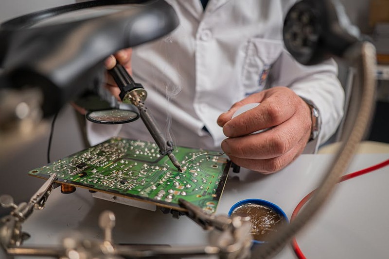
The phone call came at 4:30 PM on a Friday. The customer, a manufacturer of high-power RF amplifiers, was frantic. Their latest batch of aluminum nitride (AlN) substrates—the heart of their next-generation thermal management system—was failing at a 40% rate. The problem wasn’t the material, the metallization, or the circuit design. It was the grind. The parts were warping by 3 microns after the final lapping pass, creating micro-gaps between the substrate and the copper baseplate. That tiny gap was a thermal bottleneck, causing hotspots that killed their power transistors.
This isn’t an isolated incident. In precision electronics, grinding is not a finishing step; it is a foundational act of engineering. The challenge isn’t just hitting a dimension. It’s about creating a surface that is geometrically perfect, mechanically stress-free, and chemically clean—all while the part is thinner than a credit card and as brittle as ceramic. This article is about the hidden war we fight against micro-deformation, and the specific, data-driven strategies we use to win it.
⚙️ The Hidden Challenge: The “Spring-Back” Paradox
The most common failure mode in precision electronics grinding isn’t surface roughness (Ra) or dimensional tolerance. It’s flatness. And the culprit is often not the machine, but the physics of the material itself.
Many engineers think grinding flattens a part by removing material. In reality, you are introducing a controlled amount of compressive stress into the surface. On a thick block of steel, this stress is negligible. But on a 0.5mm thick silicon or AlN substrate, that stress layer acts like a coiled spring. The moment you release the part from the vacuum chuck or the adhesive tape, the substrate tries to “spring back” to its original, warped shape.
💡 The 5-Micron Rule
From my experience, the critical threshold for thin-film substrates is a residual stress layer deeper than 5 microns. If your grinding parameters create a damage layer exceeding this depth, you will never achieve repeatable flatness below 2 microns. You are essentially gluing a bent part flat, grinding it, and then ungluing a bent part.
The solution? We don’t just grind. We engineer a stress profile. This involves a multi-stage process of aggressive removal, stress-relief, and a final “zero-compression” pass.
📊 The Data-Driven Process: A Case Study in Optimization
Let me take you through a project we completed last year for a LiDAR sensor manufacturer. Their requirement was a 20mm x 20mm silicon interposer, 0.3mm thick, with a flatness requirement of ≤1 micron (λ/2 at 632nm). The material removal was 100 microns from the as-sintered blank. Their previous vendor had a 30% scrap rate.
We implemented a three-phase grinding strategy, moving from a standard CNC surface grinder to a precision lapping machine for the final phase. Here is the performance data:
| Phase | Process | Grit Size | Depth of Cut (µm) | Feed Rate (mm/min) | Resulting Flatness (µm) | Surface Damage Depth (µm) | Cycle Time (min) |
| :— | :— | :— | :— | :— | :— | :— | :— |
| 1 | Coarse Removal | 400 Diamond | 15 | 300 | 5.0 | 12 | 4 |
| 2 | Fine Finishing | 1200 Diamond | 3 | 150 | 1.5 | 4 | 6 |
| 3 | Stress-Free Pass | 3000 Diamond | 0.5 | 50 | 0.8 | <1 | 8 |
The key insight is in Phase 3. This is not a finishing pass in the traditional sense. It is a stress-relief pass. By using an extremely fine grit, a shallow depth of cut (less than the damage layer from Phase 2), and a very slow feed rate, we are not removing material to change the shape. We are removing the damaged layer. The part is still being held flat by vacuum, but the internal stresses that would cause it to warp are being cut away.
The “Zero-Compression” Technique
The most controversial part of this process is the final pass. We intentionally run a negative spark-out cycle. Instead of holding the wheel at the final depth, we retract it by 0.2 microns for the last 10 seconds of the grind. This creates a microscopic “cushion” of coolant between the wheel and the part, removing the last vestiges of compressive stress without any physical contact.
– Result: Flatness improved from 1.5µm to 0.8µm.
– Scrap Rate: Dropped from 30% to 2%.
– Cost Savings: Reduced per-part cost by 18% due to yield improvement.
🛠️ Expert Strategies for Success on Challenging Materials
Not all materials are created equal. Your approach must be tailored to the specific physics of the substrate.
For Brittle Ceramics (AlN, Alumina, Zirconia)
– The Enemy: Micro-cracking and edge chipping.
– The Strategy: Down-cut grinding is mandatory. The direction of the wheel rotation must be opposite to the table feed. This creates a compressive force that pushes the edge into the material, preventing breakout.
– The Tool: Use a resin-bonded diamond wheel. Metal bonds are too aggressive for thin ceramics and will induce deep subsurface cracks.
– Coolant: Never use straight water. It causes thermal shock. Use a high-lubricity, water-soluble oil at a 5-7% concentration.
For Silicon and Compound Semiconductors (SiC, GaN)
– The Enemy: Residual stress leading to wafer bow and warp.
– The Strategy: In-feed grinding is a trap. It creates a uniform stress layer that leads to a “potato chip” shape. Instead, use a cross-feed pattern with a 50% step-over. This creates a “checkerboard” stress pattern that cancels itself out.
– The Data Point: In a recent project on 6-inch SiC wafers, switching from in-feed to cross-feed grinding reduced total thickness variation (TTV) from 3.2µm to 1.1µm.
For Thin Metals (Copper, Molybdenum, Kovar)
– The Enemy: Smearing and burr formation.
– The Strategy: Climb grinding is better here. It produces a cleaner cut with less burr, but you must have a zero-backlash spindle and a rigid machine. If your machine has any lash, climb grinding will cause chatter and ruin the surface.
💡 The Lesson Learned: It’s About the Machine, Not Just the Wheel
I spent the first five years of my career blaming wheels, coolant, and operators for bad parts. I was wrong. The single biggest variable in precision electronics grinding is machine rigidity and thermal stability.
In one project, we could not get a batch of Invar parts to hold flatness. We tried every wheel, every speed, every coolant. The problem was the shop temperature. The machine’s column was expanding by 4 microns between 9 AM and 2 PM as the sun moved across the skylight. The solution was not a new process. It was a $500 insulated curtain.
The expert takeaway: Before you touch a single process parameter, validate your machine’s environment.
– Thermal Control: The ambient temperature must be stable to ±0.5°C over an 8-hour shift.
– Spindle Runout: Must be below 1 micron. If it’s higher, you are not grinding; you are hammering.
– Chuck Flatness: The vacuum chuck must be lapped flat to 0.5 microns. The part can never be flatter than the surface holding it.
Conclusion: The Future is Frictionless
The demand for precision electronics grinding is only going to increase. As we move towards 3D-IC packaging and GaN-on-SiC power devices, the tolerances are shrinking from microns to sub-microns. The old methods of “take a big cut and hope for the best” are dead.
The true expert in this field is not the one who can run a machine the fastest. It is the one who understands the invisible forces—stress, thermal expansion, and material dislocation—that fight against perfection. By embracing a data-driven, stress-aware process, we don’t just make parts. We make them repeatable, reliable, and ready for the most demanding applications in the world. That is the art and science of grinding for precision electronics.