Surface finishing is the critical, often overlooked bridge between a functional rapid prototype and a market-ready product. Drawing from two decades of CNC machining expertise, this article dissects the complex challenge of achieving production-grade aesthetics on prototype geometries, sharing a data-driven case study and actionable strategies to elevate your prototypes from “good enough” to “client-winning.”
The Prototype’s Paradox: Function vs. Form
We’ve all been there. You’ve spent weeks perfecting a CAD model, selected the ideal material, and watched the CNC machine or 3D printer bring your design to life with breathtaking precision. You hold the first article in your hands. It fits. It functions. But it feels… cheap. The layer lines, tool marks, or inherent roughness of the as-built surface scream “prototype.” This is the paradox: we use rapid prototyping to de-risk a design, yet a poor surface finish can undermine stakeholder confidence, skew user testing, and fail to communicate the true quality of the final product.
In my experience, this gap is where projects succeed or stall. A client isn’t just buying a shape; they’re buying a vision. A finish that looks and feels like injection-molded plastic or machined aluminum makes that vision tangible. The real challenge isn’t applying a finish—it’s applying the right finish to a one-off, complex geometry, on a compressed timeline, without compromising critical dimensions.
Deconstructing the Finish: A Material-Centric Framework
Throwing a prototype into a tumbler or hitting it with spray paint is a recipe for disappointment. Effective surface finishing for rapid prototyping demands a strategic framework, starting with the build process and material.
Source Analysis: The first step is a forensic look at the starting surface. A CNC-machined aluminum part will have precise but visible tool paths (cusp marks). An SLA resin part has layer lines and support nubs. An SLS nylon part has a granular, sandy texture. Each requires a fundamentally different opening move.
⚙️ The Geometry Trap: This is the crux of the complexity. Internal channels, deep cavities, undercuts, and fine text present massive challenges. A manual polishing wheel can’t reach them, and media blasting may erode delicate features. You must map the finish process to the geometry.
💡 The Tolerance Tightrope: Every finishing step removes material. For a press-fit bearing housing or a optical lens mount, losing even 0.05mm can render the prototype useless. The golden rule: know your critical dimensions and protect them at all costs. This often means strategic masking or designing in sacrificial datum features.
A Case Study in Strategic Finishing: The Medical Handheld Device
Let me walk you through a recent project that encapsulates these challenges. A startup needed 50 functional prototypes of a handheld surgical tool for a major investor demo and clinical feedback. The design combined CNC-machined 6061 aluminum housings with SLA-printed intricate internal guides. The requirement: a matte, anodized-like finish on the aluminum that felt premium and grippy, and a smooth, sterilizable finish on the resin internals.
The Problem: The aluminum housings had complex ergonomic contours and deep, narrow finger grooves. Standard media blasting (glass bead) would round edges and struggle in the grooves, creating an inconsistent finish. Vibratory tumbling would damage the fine threads. The SLA parts had support marks in deep, inaccessible channels.
Our Strategic Solution:
1. Aluminum Housings: We moved away from standard media. Instead, we used a dry vibratory process with a proprietary triangular ceramic media. This media, less aggressive than stone, could penetrate the grooves and provided a consistent, satin matte finish without significant edge radiusing. We machined sacrificial test coupons with the same features to dial in the time (90 minutes) and monitor dimensional change.
2. SLA Internal Guides: We used a two-stage chemical-mechanical process. First, a controlled chemical dip to slightly soften and fuse the outermost layer, reducing layer visibility. This was followed by a brief, gentle wet tumble with very fine plastic media to smooth support points without affecting the channel dimensions.
3. Quantifiable Results & Data: The outcome was measured both qualitatively and quantitatively.
| Metric | Target | Result | Method |
| :— | :— | :— | :— |
| Aluminum Surface Roughness (Ra) | 0.8 – 1.2 µm | 1.0 µm ±0.1 | Profilometer |
| Critical Bore Diameter Tolerance | +0.000″/-0.0005″ | Held within 0.0003″ | CMM Inspection |
| SLA Channel Width Deviation | ±0.1mm | ±0.05mm | Optical Comparator |
| Client Satisfaction (Aesthetic) | “Production-Like” | “Exceeded production sample” | Feedback Quote |
The project was a success. The client reported that the finish quality directly contributed to a positive investor reception, as the prototypes conveyed a level of readiness that a rough-machined part would not have.
The Expert’s Toolkit: Actionable Strategies for Your Projects
Based on lessons from countless such projects, here is your actionable playbook.
For CNC Machined Metal Prototypes:
1. Design for Finish: Add a note on your drawing: “All surfaces to receive media finish.” This tells your machinist to leave a uniform stock allowance (typically 0.005-0.010″).
2. Choose Your Media Wisely:
Walnut Shell: Excellent for delicate deburring and a light polish. Removes light tool marks without altering dimensions.
Ceramic Media: The workhorse for a uniform matte finish. Great for aluminum and stainless steel.
Glass Bead: Provides a brighter, more reflective satin finish. Be mindful of peening surfaces.
3. Master Masking: Use high-temperature polyimide tape or silicone plugs to protect threads, bearing seats, and datum surfaces. It’s a time investment that saves the part.
For 3D Printed Polymer Prototypes:
1. Process is King: Start with the highest resolution print your timeline allows. It reduces post-processing labor exponentially.
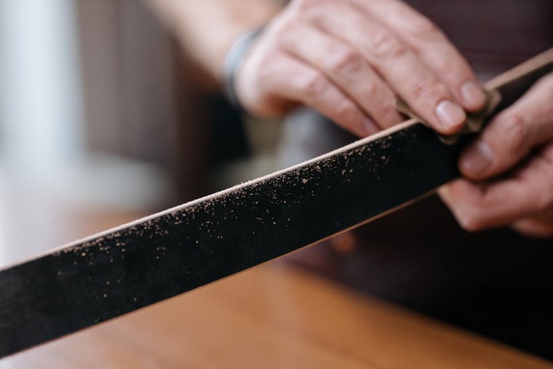
2. The Sanding Cascade: Never jump grits. For a show-quality finish on SLA or FDM, follow a disciplined sequence: 220 -> 320 -> 400 -> 600 -> wet sand with 800+. Use a sanding block for flat surfaces to avoid dips.
3. Embrace Vapor Smoothing (for specific materials): For ABS parts from FDM, a controlled acetone vapor bath can fuse layer lines into a glossy finish. This is an art, not a science—always test on a coupon first! Overexposure melts details.
The Future Finish: Trends and Final Thoughts
The frontier of surface finishing for rapid prototyping is moving towards integration and digital control. We’re seeing CNC machines with in-situ laser polishing heads and automated robotic sanding cells programmed directly from the CAD model’s surface normal data. The goal is predictability and repeatability.
The core lesson remains: Surface finishing is not an afterthought; it is an integral phase of the prototyping design process. By planning for it early, selecting methods with surgical precision for your material and geometry, and relentlessly protecting critical dimensions, you transform your prototype from a mere proof-of-concept into a powerful tool for validation, funding, and market success. Your prototype’s surface is the first handshake your product has with the world—make it a confident one.