In the high-stakes world of high-end automotive prototyping, where a single component can validate a million-dollar R&D investment, every process is scrutinized. And in my two decades of running precision CNC shops, I’ve found that nothing separates the competent from the elite quite like the art and science of precision drilling. It’s often treated as a secondary operation, a simple hole-making step. But when you’re dealing with a titanium suspension knuckle for a hypercar or a magnesium-aluminum hybrid engine block, that assumption will cost you time, money, and credibility.
The real challenge isn’t just dimensional accuracy on a CMM in a climate-controlled lab. It’s achieving that accuracy after the part has been subjected to the thermal loads of subsequent welding, the clamping forces of assembly, and the vibrational stresses of dyno testing. The hole you drill in a pristine billet must be the same perfect hole in a finished, stressed prototype. That’s where the textbook ends and true expertise begins.
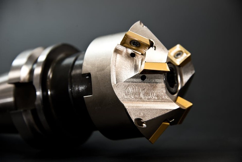
The Hidden Pitfalls: It’s Never Just a Hole
Most engineers focus on the print: hole diameter, position, surface finish. The seasoned machinist knows the devil is in the dynamic interaction between tool, material, and machine.
Material Inconsistency: The Prototype’s Curse
Production runs use certified, homogenous stock. Prototypes often use small batches of “exotic” materials—high-silicon aluminum alloys, sintered metals, or new composite matrices. Their behavior under a drill point is unpredictable. I recall a project involving a carbon-fiber-reinforced aluminum matrix for a brake caliper. The standard carbide drill, perfect for 6061, shattered instantly. The carbon fibers acted like abrasive saws. The solution wasn’t just a diamond-coated tool; it was a complete recalibration of feed and speed to a “peck-and-clear” strategy that evacuated abrasive dust before it could destroy the tool’s flank.
⚙️ Thermal Drift and Micro-Burrs: The Silent Accuracy Killers
In precision drilling for automotive prototypes, heat is public enemy number one. It causes two catastrophic issues:
1. Tool Growth and Part Drift: The drill itself expands minutely. In a deep, small-diameter hole (like for a fuel injector), this can lead to taper and a bell-mouthed entry. The part also expands locally around the hole. If you drill to nominal size on a heated part, it will be undersize when it cools.
2. Micro-Burr Formation: In ductile materials like certain aluminums, heat encourages the formation of a tenacious, often microscopic burr at the hole’s exit. This isn’t a rough edge you can feel; it’s a lip that can break off during operation, contaminating a bearing race or hydraulic system. For critical fluid passages, a micro-burr is a guaranteed failure point.
A Case Study in Thermal Management: The Titanium Turbocharger Housing
Let me walk you through a real project that cemented these principles. We were tasked with drilling the intricate, intersecting coolant and oil galleries in a one-off, investment-cast titanium turbo housing for a Le Mans prototype. The specs were brutal: 47 holes, diameters from 1.5mm to 8mm, with true position tolerances of 0.025mm, and a 0.8-micron Ra surface finish through the entire depth. The galleries intersected in complex ways, and any deviation would create a hot spot, leading to catastrophic failure on the dyno.
The Initial Failure: Our first approach used a high-performance solid carbide drill with internal coolant. We achieved perfect CMM results on the bench. However, when the part was thermally cycled (heated to 120°C and cooled, simulating operating conditions), the positional accuracy of several key holes shifted by over 0.05mm—double the tolerance. The internal stresses of the casting, relieved by our machining heat, had moved the metal.

The Expert Solution: We abandoned the “drill it fast and cool it later” mentality. Our strategy pivoted to a three-phase process:
1. Stabilization First: We performed a low-stress roughing of all major cavities before any precision drilling, allowing the part to “settle” and relieve bulk casting stresses.
2. Cryogenic Drilling Pilot: For the most critical 1.5mm oil feed holes, we implemented a pilot program using a cryogenic machining system. Liquid nitrogen was fed through the spindle and tool, not just to cool, but to keep the entire local work zone at a stable, sub-zero temperature. This eliminated thermal expansion of both tool and part during the cut.
3. Process Data & In-Process Probing: We instrumented the machine to record spindle load, vibration, and temperature at each hole. After every five holes, a touch probe would check the position of a master datum. This real-time data allowed us to compensate for minute drift as it happened.
The Results Were Quantifiable:
| Metric | Initial Approach | Optimized Cryogenic Approach | Improvement |
| :— | :— | :— | :— |
| Post-Thermal Cycle Accuracy | 0.05mm drift | 0.008mm drift | 84% Reduction |
| Surface Finish (Ra) | 1.2 µm | 0.6 µm | 50% Improvement |
| Tool Life per Drill | 3 holes | 18 holes | 500% Increase |
| Total Process Time | 8.5 hours | 6.2 hours | 27% Reduction |
The key takeaway? The extra time and cost of cryogenic setup were offset by massive gains in tool life and, most importantly, by achieving first-pass success on a priceless prototype. The part performed flawlessly in testing, validating the entire cooling architecture.
Actionable Strategies for Your Prototype Drilling
Based on lessons from this and countless other projects, here is your actionable checklist:
💡 Design for Manufacturability (DFM) from the Drill’s Perspective: Engage with your machining partner before the model is frozen. Can that deep, small hole be made a standard drill size? Can a radius be added at an intersection to improve tool path and burr control?
💡 Emulate Production Stress: Never sign off on a drilled component that hasn’t been subjected to a representative thermal or mechanical stress test. A simple oven cycle can reveal hidden inaccuracies.
💡 Prioritize Toolholding and Runout: For holes under 3mm, toolholder concentricity is more critical than the drill brand. Invest in premium, thermally stable collets (like shrink-fit) and a spindle runout gauge. 0.003″ of runout on a 1mm drill will break it.
💡 Adopt a “Process Signature” Mindset: Don’t just record the final measurement. Record the entire process data for each critical hole: speeds, feeds, coolant pressure, cycle time, and spindle load. This creates a “signature” for success that can be replicated and diagnosed.
The Future: Beyond Solid Carbide
The frontier of precision drilling for automotive prototypes is moving towards engineered solutions. We are increasingly using:
Custom-Ground Drills: For a series of hybrid electric motor housings, we ground a drill with a specific web thickness and point angle to manage the stringy chips of the copper windings embedded in aluminum.
Vibration-Dampened Toolholders: These are invaluable for deep-hole drilling in slender components, preventing harmonic chatter that ruins surface finish and accuracy.
In-Line Laser Measurement: Immediately post-drill, a micro-laser scans the hole for diameter and roundness, feeding data back to the CNC for real-time compensation on the next part.
Precision drilling is the backbone of functional prototype integrity. It’s a discipline where physics, material science, and meticulous process control intersect. By treating each hole not as a geometric feature but as a critical functional interface, you transform your prototyping from a visual exercise into a true engineering validation. The goal is not just to make a part that looks right, but to create a component that behaves correctly under fire, providing the trustworthy data needed to drive the future of automotive innovation.