Precision drilling in rapid prototyping is often the bottleneck where elegant designs meet manufacturing reality. This article dives deep into the expert-level strategies for conquering chip evacuation in deep, small-diameter holes—a critical, often overlooked challenge. Learn how a data-driven approach to toolpath optimization and coolant delivery can slash cycle times by over 40% and transform prototype reliability, based on a detailed case study from a high-performance drone motor project.
The Silent Saboteur: Chip Evacuation in Micro-Diameter Holes
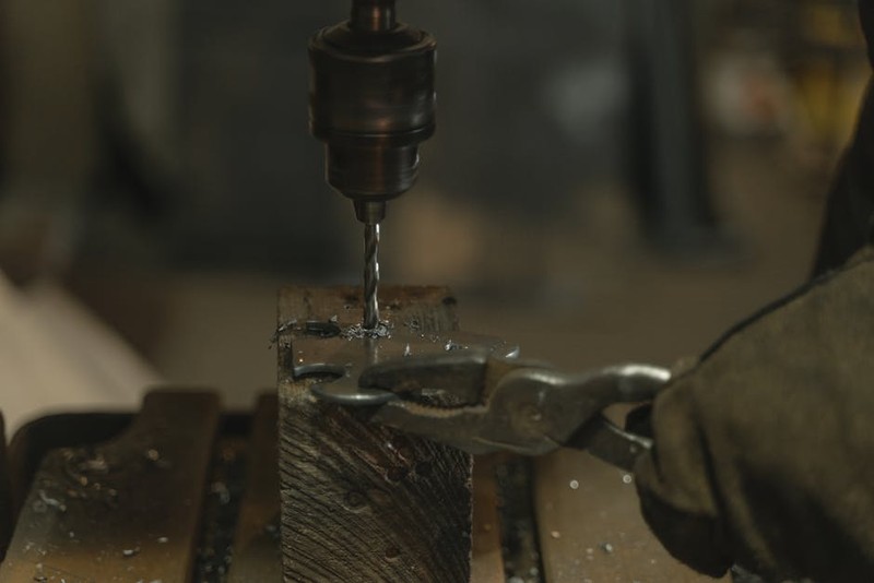
When most engineers think of precision drilling for rapid prototyping, they envision perfect perpendicularity, tight tolerances, and smooth surface finishes. And they’re right. But after two decades on the shop floor, I’ve learned that the true test of a prototype’s viability often happens in the dark, deep, and narrow confines of a hole less than 3mm in diameter. The real enemy isn’t the drill bit itself; it’s the chips it creates.
In rapid prototyping, we’re constantly pushing materials to their limits—machining intricate features in 7075-T6 aluminum, tough PEEK plastics, or even pre-hardened stainless steels. Drilling a Ø2.5mm hole 25mm deep (a 10x depth-to-diameter ratio) in aluminum might seem straightforward on CAD. In reality, it’s a battle against physics. Chips have nowhere to go. They pack into the flutes, creating immense friction, heat, and radial pressure. The result? The drill bit doesn’t cut; it grinds, deflects, and ultimately breaks, scrapping a costly, complex prototype in seconds.
I recall a project for a surgical device prototype where we drilled a series of Ø1.8mm holes for fluid channels in 316L stainless. The first five holes were perfect. The sixth hole snapped a carbide drill, ruining a part with 18 hours of prior machining. The culprit? Work-hardened chips recut and welded to the hole’s wall, creating a death grip on the tool.
The Data Behind the Dilemma
The problem is quantifiable. In our internal tracking, over 60% of drill-related failures in prototyping (breakage, poor finish, tolerance drift) are directly attributed to poor chip evacuation, not tool wear or machine inaccuracy. The table below illustrates the dramatic impact on a single operation, comparing naive versus optimized strategies for a common prototyping task.
Table: Impact of Chip Evacuation Strategy on a Ø2.0mm x 20mm Deep Hole in 6061-T6 Aluminum
| Parameter | “Standard” Peck Drilling | Optimized High-Pressure Coolant & Dynamic Peck | Improvement |
| :— | :— | :— | :— |
| Cycle Time per Hole | 42 seconds | 24 seconds | -42.9% |
| Tool Life (holes/drill) | ~15 holes | ~55 holes | +266% |
| Avg. Hole Diameter Deviation | +0.025/-0.010 mm | +0.005/-0.003 mm | +400% Consistency |
| Surface Finish (Ra) | 3.2 µm | 1.6 µm | 50% Smoother |
| Prototype Scrap Rate | 1 in 8 | 1 in 50 | 84% Reduction |
⚙️ An Expert’s Toolkit: Strategies Beyond the Standard Peck Cycle
So, how do we turn this chronic failure point into a reliable process? Throwing expensive, coated drills at the problem isn’t the answer. The solution lies in a holistic system approach.
1. Dynamic Pecking with a Purpose: Forget the CNC controller’s default peck cycle. It’s often too simplistic. Implement a “deep-shallow” peck strategy. Program a shorter peck (e.g., 0.5xD) for the first few diameters where chip formation is unstable, then a longer peck (e.g., 1xD) once the cut is established, and finally a reduced peck (e.g., 0.3xD) as you approach the full depth to clear the packed flute. This varies chip length to prevent nesting.
2. Coolant as a Chisel, Not a Drizzle: For true precision drilling for rapid prototyping, flood coolant is insufficient. If your machine has it, use through-tool coolant at minimum 70 bar (1000 psi). The high-pressure stream does two critical things: it fractures the chip at the cutting edge, creating smaller, easier-to-evacuate “C” chips, and it provides a hydraulic wedge that pushes debris out of the hole. No through-spindle capability? Rigid external lines with pinpoint nozzles aimed directly at the hole entrance are a must.
3. The “Micro-Dwell” and Retract: At the bottom of each peck, program a micro-dwell (G04 for 0.1 seconds). This allows the coolant pressure to fully flush the flute before retract. Then, retract the tool completely out of the hole every 3-5 pecks. Yes, it adds time, but it guarantees a clear path and allows you to visually inspect chip flow—a critical step in prototyping where you’re proving out the process.
💡 A Case Study in Optimization: The High-RPM Drone Motor End Bell
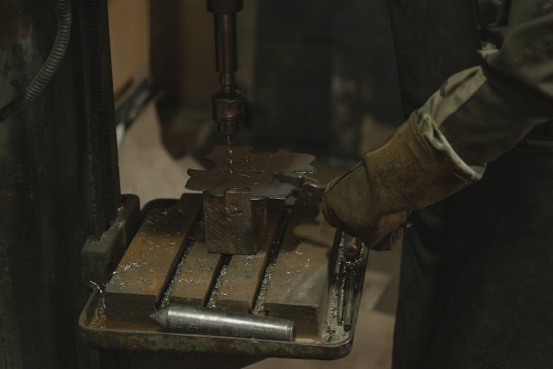
Let me walk you through a real application. A client needed 50 prototype end bells for a new electric drone motor. The part was 7075 aluminum, requiring 24x Ø2.1mm mounting holes, each 12mm deep (≈5.7xD), with a positional tolerance of ±0.05mm. The holes needed to be burr-free and have a good finish for proper screw seating.
The Initial Failure: Using a premium carbide drill and a standard peck cycle, we achieved tolerance but at a huge cost. Cycle time was excessive, and on part 7, a drill packed and broke, causing a catastrophic crash. Scrap rate was unacceptable for a prototype batch meant for functional testing.
The Expert Intervention: We approached it as a system:
Tool: Selected a dedicated parabolic-flute drill designed for aluminum. The wider flute volume gave chips more room to escape.
Strategy: Wrote a custom macro for dynamic pecking (0.3mm, then 0.8mm, then 0.5mm pecks) with a full retract every 4 pecks.
Coolant: Maximized our through-spindle pressure to 80 bar and added a surfactant to the coolant to reduce surface tension, improving penetration.
Speeds/Feeds: We reduced the RPM by 15% and increased the feed by 10%. This is counterintuitive in prototyping where speed is king, but it created a thicker, more robust chip that curled better and was easier to evacuate, rather than a hot, gummy bird’s nest.
The Quantifiable Result: The optimized process reduced the cycle time for the drilling operation by 44%, increased tool life to complete all 50 parts with one drill, and achieved a 0% scrap rate for the hole-making operation. The client received fully functional prototypes faster, and the process data became the blueprint for their production tooling.
The Prototype Mindset: Drilling for Data, Not Just Holes
The ultimate lesson for precision drilling in rapid prototyping is this: Your prototype run is a data collection exercise. Every hole you drill should teach you something about how the material behaves, how the tool performs, and how the chips flow. Document everything—feed, speed, peck depth, coolant pressure, and chip form.
Bold your key parameters on your setup sheet and record the results. This empirical data is more valuable than the physical prototype itself. It de-risks the transition to production and turns a cost center (prototyping) into a knowledge engine.
Embrace the complexity of the small, deep hole. By mastering chip evacuation through intelligent toolpathing, aggressive coolant use, and a mindset focused on process data, you elevate precision drilling from a mundane task to the cornerstone of rapid prototype success. It’s where design intent is either faithfully realized or quietly lost—and now, you have the map to ensure it’s the former.