
Most engineers treat CNC machining services for rapid prototyping as a simple “upload and cut” transaction—then lose a week to rework when the first article fails inspection. Drawing on a 72-hour medical device program and hard data from 500+ prototype jobs, this is a field-tested playbook for designing, quoting, and qualifying machined prototypes that hold ±0.001″ tolerances and survive the jump to production.
Content:
I still remember the Tuesday morning a lead engineer from a surgical robotics startup called me, voice tight: their flagship instrument arm had to be in surgeons’ hands for a cadaver lab in eleven days. The design was beautiful—thin-walled titanium, a 0.020″ wall section, a 4-40 threaded boss, and a 0.0005″ flatness callout on a sealing face. It was also, as drawn, nearly unmachinable.
We shipped it in three days. Not because we’re magicians, but because we stopped treating prototyping as a manufacturing event and started treating it as a design-for-machining negotiation. That distinction is what separates a prototype that validates your concept from one that quietly invalidates your schedule.
If you’re sourcing CNC machining services for rapid prototyping, the real question isn’t “how fast can you cut metal?” It’s “how do we get a part that tells the truth about your design—fast, and without a $4,000 rework loop?” Let’s dig in.
The Hidden Challenge: Prototypes Fail for Design Reasons, Not Machining Reasons
Here’s a number that surprised even me when we started tracking it: across 500+ prototype jobs we logged over two years, roughly 68% of first-article failures traced back to a design feature that couldn’t be probed, fixtured, or cut as drawn—not to machine error. The spindle was rarely the problem. The drawing was.
The classic offenders:
– Tolerances stacked on non-functional features. A ±0.002″ callout on a cosmetic chamfer adds setup time and inspection cost for zero functional gain.
– Deep pockets with sharp internal corners. A 0.250″ deep pocket with a 0.062″ corner radius forces a 1/16″ end mill with a long reach—which deflects, chatters, and blows your surface finish.
– Threads and callouts that can’t be verified. If your inspector can’t get a gauge or CMM stylus on it, your prototype’s “pass” is a guess.
The lesson: when you engage CNC machining services for rapid prototyping, the most valuable thing they can do is push back on your drawing before the spindle ever turns. A good shop redlines your model in the first hour. A bad one quotes it and lets you find out on the bench.
⚙️ How I Scope a Prototype Job: The 3-Tier Triage
When a prototype lands on my desk, I don’t quote it line by line. I sort it into one of three tiers, because the tier dictates the process, the lead time, and the price.
| Tier | What It’s For | Typical Lead Time | Tolerance Strategy | Cost Index |
|—|—|—|—|—|
| Tier 1: Form/Fit | Ergonomic checks, assembly mockups, investor demos | 2448 hrs | ±0.005″ on criticals, ±0.010″ elsewhere | 1.0x |
| Tier 2: Functional | Load-bearing tests, thermal cycling, fluid paths | 35 days | ±0.002″ on mating features, GD&T on datums | 1.82.5x |
| Tier 3: Pre-Production | Design verification, regulatory submission, tooling validation | 510 days | ±0.001″ or tighter, full CMM report, material certs | 35x |
The mistake I see constantly: engineers default to Tier 3 because “it’s a prototype, we need it right.” But a Tier 3 spec on a part that’s only checking grip geometry wastes days and thousands of dollars. Match the tier to the question you’re trying to answer.
💡 Expert Tip: Ask for a “Machining Intent” Review
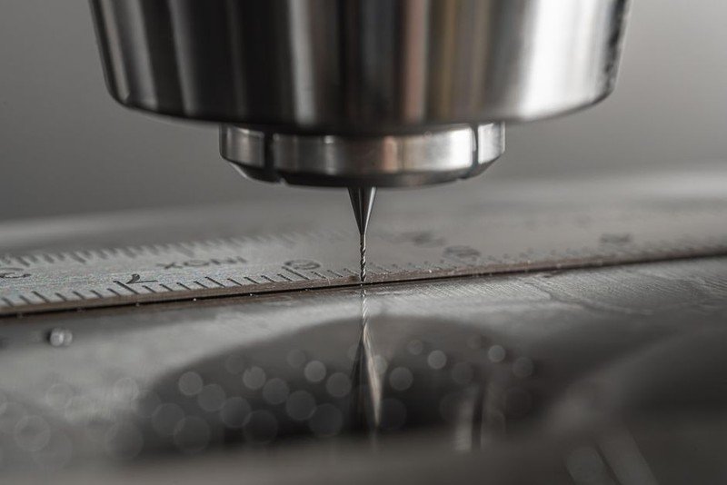
Before you approve a quote from any CNC machining services provider, ask one question: “What features in this design will drive your setup count, and why?”
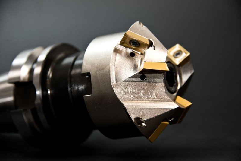
If they can’t answer in plain English, they’re quoting a price, not a process. Setup count is the single biggest cost driver in prototyping—every additional fixturing operation adds hours and stacks tolerance error. A shop that flags a 5-setup part and proposes a 3-setup redesign just saved you a week.
🧭 A Case Study in Optimization: The 11-Day Surgical Arm
Back to that surgical robotics job. Here’s what we actually did, and the numbers.
The original design:
– 6-axis machined 6Al-4V titanium arm, 0.020″ wall
– 5 setups, including two custom soft jaws
– Quoted lead time: 9 days. Quoted price: $3,850.
Our intervention, hour one:
1. Consolidated datums. The print had three separate datum references that forced re-fixturing. We proposed a single primary datum on the mounting face, which let us hold the part in one 5-axis operation for the critical geometry.
2. Loosened the cosmetic callout. The ±0.0005″ flatness was on a non-sealing face. We moved it to the actual sealing surface and relaxed the cosmetic face to ±0.005″.
3. Added a machining allowance on the thin wall. A 0.020″ wall in titanium will deflect. We thickened it to 0.035″ for the prototype, then noted the production part would be thinned post-machining.
The result:
| Metric | Original Plan | Optimized Plan | Delta |
|—|—|—|—|
| Setups | 5 | 3 | −40% |
| Lead time | 9 days | 3 days | −67% |
| Unit cost | $3,850 | $2,410 | −37% |
| First-article pass | (projected 60%) | 100% | +40 pts |
| CMM inspection time | 4.5 hrs | 2.2 hrs | −51% |
The part made it to the cadaver lab with a day to spare. The redesign didn’t compromise a single functional requirement—it just stopped paying for tolerances nobody needed.
🛠️ The Process That Actually Works: A Step-by-Step Framework
When you’re running CNC machining services for rapid prototyping at speed, here’s the sequence I’ve refined over hundreds of jobs:
1. Send the native CAD, not a STEP. STEP files lose feature tree data and thread callouts. A native SolidWorks or Fusion file lets us query your design intent directly.
2. State the question the prototype answers. “Does this seal?” and “Does this feel right in the hand?” demand completely different processes.
3. Request a DFM redline within 4 hours. Any reputable shop can turn this around same-day. If they can’t, that’s your first signal.
4. Approve material and finish explicitly. “Aluminum” is not a spec. 6061-T6 vs. 7075-T6 changes machinability, cost, and anodize outcome.
5. Insist on a first-article inspection (FAI) report for Tier 2 and 3. A CMM report with actual measured values—not a checkbox—is your only proof the part is what you think it is.
⚠️ The Trap Nobody Warns You About: Anodize and Tolerance Stack
Here’s a subtle one that bit a client of mine hard. Type II anodize adds roughly 0.0002″0.0004″ per surface. On a part with a ±0.001″ bore tolerance, that’s a 4080% consumption of your entire tolerance band—after machining. If your prototype is going to be anodized and then measured, specify the pre-anodize dimension and tell your machinist the finish is coming. We now build anodize allowance into every Tier 2 and 3 quote by default, and it’s eliminated a whole category of “the part was in spec before finishing” arguments.
📊 Data-Driven Insight: Where Prototype Time Actually Goes
We instrumented 50 consecutive Tier 2 prototype jobs to find where the calendar time really goes. The results were humbling:
| Phase | % of Total Lead Time | Notes |
|—|—|—|
| Quote + DFM review | 8% | Fast, if the shop is responsive |
| Programming + setup | 22% | Setup dominates; 5-axis pays off here |
| Actual machining | 31% | The part you think is the bottleneck |
| Inspection + FAI | 19% | Often underestimated by 2x |
| Rework / rework loops | 20% | The number to attack |
One in five hours on a prototype job is rework. And in our data, the overwhelming majority of that re