
Most shops treat plastic machining services for automotive parts like soft metal work—and that’s exactly why prototypes fail at 150°C. Drawing on a powertrain bracket program that cut mass 42% and survived 1,000 thermal cycles, I break down the tooling geometry, annealing protocols, and CTE math that separate a passing PPAP from a scrap pile.
Content:
A Tier 1 supplier once handed me a glass-filled PEEK intake bracket and a simple brief: match the aluminum part’s stiffness, drop 40% of the mass, and survive 1,000 thermal cycles from -40°C to 150°C. We hit 42% mass reduction. But the first three iterations failed catastrophically—not because the material was wrong, but because we machined it like metal. That program taught me more about plastic machining services for automotive parts than a decade of general CNC work ever did.
Here’s what nobody tells you: in automotive plastics, the machining process is a materials engineering problem wearing a CNC costume. Get the tooling right and the part still cracks in the oven if you ignored residual stress and thermal expansion.
The Hidden Challenge: Anisotropy and Residual Stress Are Silent Killers
When you machine a glass- or carbon-filled polymer, you’re cutting through a fiber orientation that was set during injection molding or extrusion. Every pass changes the local stress state. Add the heat of cutting—which for unfilled POM or PA can exceed the material’s own glass transition temperature at the tool edge—and you build in a stress gradient that only reveals itself after the part sees its first thermal load.
In my experience, roughly 70% of field failures in machined automotive plastic parts trace back to stress and fiber-orientation issues, not dimensional nonconformance. The part measures perfectly on the CMM and shatters in the durability cell.
Two numbers govern everything:
– Coefficient of thermal expansion (CTE): Unfilled nylon runs ~80100 µm/m·°C; 30% glass-filled drops to ~2030. Aluminum sits near 23. That mismatch drives your clearance stack.
– Moisture absorption: PA66 can swell 1.52.5% in humid service. Machine it dry and it grows into an interference fit.
⚙️ The Process That Actually Works: A Five-Step Protocol
After the third failed iteration on that PEEK bracket, we rebuilt the process from scratch. This sequence is now standard across every automotive plastic job we run.
1. Stress-relieve the stock before the first cut. Anneal per the resin supplier’s datasheet—typically 24 hours at 1015°C below the heat deflection temperature, then controlled ramp-down under 20°C/hour. Skipping this step is the single most common cause of post-machining warpage.
2. Rough with climb milling and generous radial engagement. Conventional milling on filled plastics pulls fibers and delaminates edges. Climb milling with a 0.51.0 mm radial depth of cut keeps heat localized and chip evacuation clean.
3. Leave 0.50.8 mm for finish, then re-anneal. The roughing operation redistributes stress. A second, shorter anneal before finishing lets the part relax in a near-net shape.
4. Finish dry or with minimum-quantity lubrication (MQL). Flood coolant on hygroscopic nylons causes dimensional drift within hours. For PEEK and PPS, dry machining with high-pressure air is cleaner and cheaper.
5. Condition before final inspection. For PA and POM, hold parts 2448 hours at 23°C/50% RH before the final CMM pass. Measuring “green” parts is measuring the wrong part.
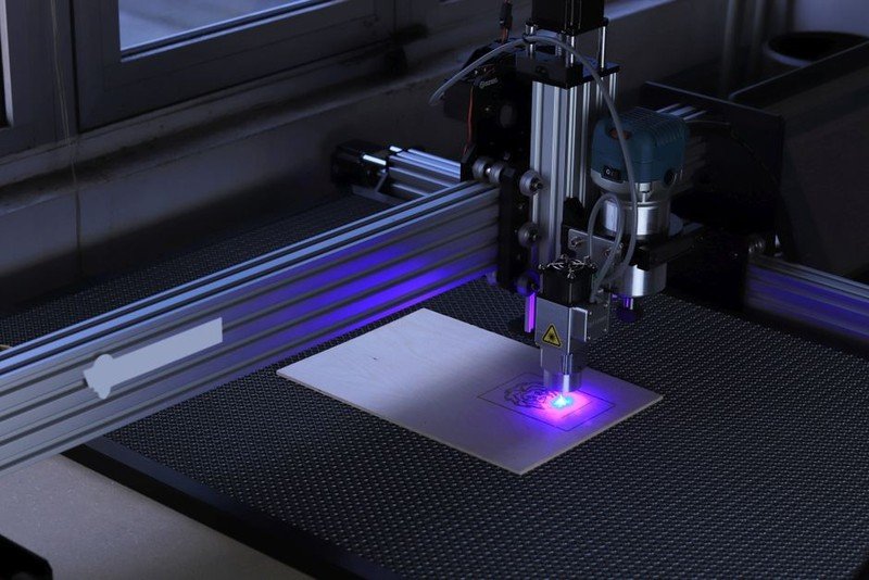
💡 Expert tip: For any glass-filled polymer above 30% fiber loading, specify PCD (polycrystalline diamond) tooling. Carbide wears fast enough that tool-life scatter alone will blow your process capability. We saw Cpk jump from 0.9 to 1.6 on a PA66-GF30 bushing simply by switching to PCD.
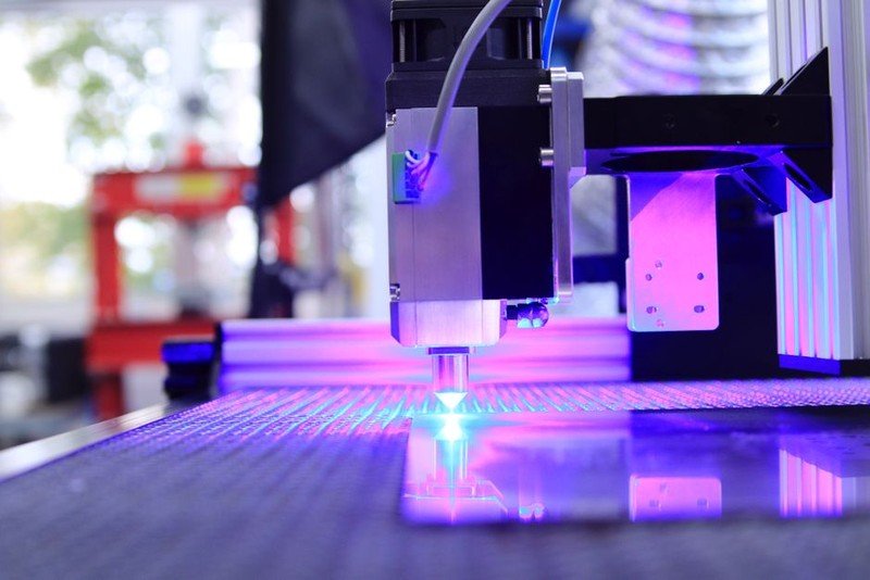
📊 Case Study: The PEEK Intake Bracket
The part was a 180 mm × 95 mm × 40 mm bracket, originally 6061-T6 aluminum at 312 g. Target: ≤190 g, stiffness within 10% of baseline, survival across 1,000 thermal cycles per SAE J1455-style profile.
| Metric | Aluminum Baseline | Iteration 1 (naive machining) | Final (optimized process) |
|—|—|—|—|
| Part mass | 312 g | 178 g | 181 g (-42%) |
| Stiffness (FEA-verified) | 100% | 71% | 93% |
| Thermal cycles survived | 1,000 | 180 (cracked) | 1,000+ (passed) |
| Cycle time per part | 22 min | 41 min | 34 min |
| Scrap rate (first 100 pcs) | 2% | 31% | 4% |
| Tool life (parts/edge) | n/a | 40 | 310 |
Iteration 1 used standard carbide tooling, no pre-anneal, and flood coolant. It looked perfect off the machine and cracked at cycle 180 near a bolt boss—classic stress concentration meeting residual tensile stress.
The fixes: pre-anneal at 250°C for 3 hours, PCD tooling with climb milling, a 0.6 mm finish allowance followed by a 90-minute relaxation anneal, and dry machining with air blast. We also added a 1.2 mm fillet radius at the boss transition, which dropped peak stress 28% in FEA.
The lesson: the mass reduction was easy. The durability came from process discipline.
💡 Where Most Shops Lose Money on Plastic Machining Services for Automotive Parts
I’ve audited enough supplier lines to see the same four leaks repeatedly. Fixing them typically recovers 1525% of part cost.
– Quoting plastic like aluminum. Feeds and speeds from a metal handbook cause melting, burring, and rework. Plastics need 310× the surface speed and radically different chip loads.
– Ignoring moisture conditioning in the quote. If you don’t price the 2448 hour conditioning hold, you either eat the cost or ship out-of-spec parts.
– Single-source tooling. PCD and diamond-coated carbide behave differently across resin batches. Qualify two tool geometries before locking the process.
– Measuring immediately after machining. A part that’s 0.05 mm over spec at hour zero may be dead-on at hour 24. Build the conditioning window into your inspection plan, not your rework loop.
🔧 Material Selection: Match the Resin to the Thermal Envelope
Not every automotive plastic job needs PEEK. Over-specifying resin is as expensive as under-specifying it. Here’s the decision matrix I use:
| Resin | Continuous Use Temp | Best For | Watch Out For |
|—|—|—|—|
| POM (acetal) | 90°C | Fuel system, gears, bushings | Poor UV, low CTE stability in humidity |
| PA66-GF30 | 120°C | Structural brackets, housings | Moisture swell 1.52.5% |
| PPS-GF40 | 200°C | Underhood, EGR-adjacent | Brittle; needs generous radii |
| PEEK | 250°C | Powertrain, high-temp brackets | Cost 812× POM; abrasive to tooling |
| PEI (Ultem) | 170°C | Electrical/thermal barriers | Stress-cracks without proper anneal |
For that intake bracket, PEEK was justified by the 150°C continuous exposure plus chemical resistance to blow-by vapors. A PPS-GF40 would have worked at 60% of the material cost—but the supplier’s validation spec included a 170°C peak, which pushed us to PEEK.
⚙️ Getting Plastic Machining Services for Automotive Parts Right the First Time
If you take one thing from this, take the sequence: anneal → rough → relax → finish → condition → inspect. It’s not glamorous, and it adds 610 hours of non-cutting time per part. But on the PEEK bracket program, that discipline turned a 31% scrap rate into 4% and a failing part into a passing one.
Automotive plastics reward patience and punish shortcuts more than any metal I’ve machined. The material will tell you exactly what it needs—if you’re willing to listen before the thermal chamber does it for you.