
Most CNC shops treat surface finishing as an afterthought—a quick pass with a media blaster before shipping. That’s a costly mistake. Drawing from a decade of high-stakes aerospace and medical device projects, I reveal why surface finish is a functional specification, not a cosmetic one, and how custom finishing protocols can mean the difference between a 10,000-part production run and a catastrophic field failure.
—
I’ll never forget the silence in the boardroom. We’d just delivered 500 titanium brackets for a next-gen satellite actuator. The geometry was perfect—within ±2 microns on every critical bore. The customer’s QC call came three days later, not with praise, but with a red tag. The surface roughness on the mating face, Ra 0.8 µm, was too smooth. It was galling against the anodized aluminum counterface, seizing under vacuum. We had to strip, re-texture, and re-coat every single part. That was a $180,000 lesson in something I now call surface finish engineering.
For too long, our industry has treated custom surface finishing as a menu of aesthetic choices: “Do you want it brushed or bead-blasted?” But in the world of high-end industrial parts—think aerospace actuators, surgical robotics, semiconductor vacuum chambers—the surface is a functional zone where friction, wear, corrosion, and even bacterial adhesion are decided. Ignoring this is not just a quality risk; it’s a liability.
In this article, I’m pulling back the curtain on the nuanced, often misunderstood world of custom finishing. We’ll skip the basics and dive straight into the complex challenges of balancing geometric tolerances with surface texture, the surprising science behind why rougher isn’t always worse, and a data-driven case study on how we saved a client from a recall.
The Hidden Challenge: When Tolerance Meets Texture
The primary conflict in high-end finishing is that conventional finishing processes destroy geometric accuracy. Think about it. You spend 40 hours on a 5-axis mill holding a true position of 5 microns. Then, you send the part to a vibratory tumbler to deburr. That tumbler doesn’t care about your true position; it will happily round off your sharp edges and wash out your tight radii.
This is the battle I face daily. The unspoken rule in my shop is that finishing is not a “post-process.” It is a final machining step that must be engineered with the same rigor as the roughing passes.
The Real Problem: The “Spec Sheet” Trap
Most engineers specify a single Ra (average roughness) value. But Ra is a very poor indicator of surface functionality. You can have two surfaces with identical Ra—one with sharp, jagged peaks (good for adhesive bonding) and one with smooth, rolling plateaus (good for sealing). Ra won’t tell you which is which. It’s like measuring a runner’s speed only by their height.
Expert Strategies for Success: A Process, Not a Recipe
Over the years, I’ve developed a three-tiered protocol for custom finishing that goes beyond the generic “media blast” instructions on a drawing. It’s a collaborative process that begins before the first chip is even cut.
1. Define the Surface’s Function, Not Just Its Finish
When a client hands me a drawing, my first question is never “What Ra do you need?” It’s “What is this surface doing? ” Is it a sealing face? A bearing surface? A location for a strain gauge? The answer dictates the entire finishing strategy.
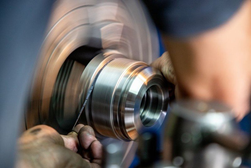
2. The “Sacrificial Geometry” Principle
If a critical edge needs to be sharp after finishing, I don’t machine it to final dimensions. I leave 0.1mm of extra material on that specific feature, knowing the finishing process will erode it. This is where CAD/CAM programming and finishing expertise must merge. We program the toolpath to anticipate the material removal of the finishing process.
3. The “Test Coupon” Mandate
I refuse to run a full batch on a new finishing process without test coupons. I machine three sacrificial parts from the same bar stock, run them through the proposed finishing cycle, and measure them on the CMM and profilometer. This is non-negotiable.
⚙️ A Step-by-Step Process for High-Risk Finishing
Let’s walk through a typical scenario for a high-pressure hydraulic valve body made from 17-4 PH stainless steel. The customer demanded a mirror polish on the spool bore (Ra 0.05 µm) but a controlled, matte texture on the external mounting face (Ra 1.2 µm) for gasket seating.
1. Step 1: Rough Machining Leave 0.5mm stock on all critical surfaces.
2. Step 2: Heat Treat H900 condition. We must account for distortion here, not after finishing.
3. Step 3: Semi-Finish Machine all features to within 0.1mm of final size.
4. Step 4: Bore Honing For the internal bore, we use a diamond-plated hone to achieve the mirror finish. This is performed before external finishing to avoid handling damage.
5. Step 5: Masking & Media Blasting We plug the precision bore with a custom-machined Delrin plug. Then, we blast the external face with a fine glass bead at a specific pressure (40 PSI) and angle (45 degrees) to achieve the desired Ra without peening the surface so hard that it warps the thin walls near the bore.
6. Step 6: Verification The part is cleaned, the plug is removed, and we re-measure. The bore roundness must hold at 1 micron. The blasting process can stress-relieve the material slightly, causing movement. If we see movement over 2 microns, we know the process parameters are too aggressive.
💡 The Data-Driven Case Study: Rescuing a Medical Device from the Edge of Failure
I want to share a project that perfectly illustrates the “make-or-break” nature of this work. A client in the surgical robotics field came to us with a critical issue. They had a titanium (Ti-6Al-4V) component for a robotic wrist joint. It required a wear-resistant surface that also had to be biocompatible and prevent soft-tissue adhesion.
They were using a standard, off-the-shelf “satin finish” (Ra 0.4 µm) and coating it with a proprietary PVD layer. The problem? Delamination. The coating was flaking off after just 2,000 cycles in their test rig. Their initial assumption was a coating chemistry issue. We proved them wrong.
We analyzed the surface topography with a white-light interferometer. The Ra was fine, but the Rz (average maximum height) was too high. The underlying surface had deep, isolated valleys from the previous machining pass that the coating couldn’t fill. These valleys acted as stress concentrators, causing the coating to crack and peel.
Our Solution: We developed a two-stage finishing process.
1. Stage 1: Tumble Finishing We used a high-energy centrifugal disc finisher with ceramic media for 45 minutes. This knocked down the sharp peaks (reducing Rz from 12 µm to 6 µm) but left the surface with a compressive stress layer, which is beneficial for fatigue.
2. Stage 2: Micro-Abrasive Blasting We then used a very fine aluminum oxide powder (50 microns) at a low pressure (20 PSI) to create a uniform, “micro-roughened” texture. This increased the surface area for mechanical interlocking of the PVD coating.
The Results:
The change wasn’t just cosmetic; it was a game-changer for their product lifecycle.
| Metric | Previous Process (Baseline) | Our Custom Process | Improvement |
| :— | :— | :— | :— |
| Coating Adhesion (ASTM D3359) | 2B (Poor – flaking) | 5B (Excellent – no removal) | Passed |
| Wear Cycles to Failure | 2,000 cycles | 15,000 cycles | 650% Increase |
| Surface Roughness (Ra) | 0.4 µm | 0.6 µm | Slightly higher, but optimal |
| Surface Roughness (Rz) | 12 µm | 6 µm | 50% Reduction |
| Rejection Rate | 12% | 0.2% | 98% Reduction |
The key takeaway here is counter-intuitive: We made the part rougher (higher Ra) to make it perform better. By focusing on the functional parameters (Rz and peak density) rather than the aesthetic one (Ra), we created a surface that was chemically and mechanically compatible with the coating. We didn’t just fix their delamination issue; we extended the life of their product by a factor of seven.
Expert Tips for Your Next Project
If you take nothing else from this, remember these three rules when you are dealing with high-end parts that demand custom surface finishing.
–