
Aerospace fitting manufacturing isn’t about holding tolerances; it’s about proving them. This article dissects how modern CNC turning services tackle the industry’s most punishing challenge—micro-deformation in thin-walled fittings—using a real project’s data, a step-by-step troubleshooting methodology, and the hard lessons learned from machining Inconel 718 at 0.0002-inch tolerances.
\n\n
The phone call came on a Tuesday afternoon. A Tier-1 aerospace supplier had a problem: a batch of 316 stainless steel hydraulic fittings—specifically, a complex union elbow with a 0.375-inch bore—was failing helium leak tests at a rate of 12%. The parts were dimensionally perfect when they left the CNC lathe. But after the final passivation step, the internal geometry was shifting by an average of 0.0008 inches. That’s enough to compromise the seal, scrap the part, and cost the client $40,000 per week in rework and downtime.
I’ve been in CNC machining for over two decades, and if there’s one thing I’ve learned, it’s that aerospace fittings are not just small parts; they are high-stakes engineering puzzles wrapped in a metal cylinder. The challenge isn’t the tight tolerances—those are a given. The real battle is against the invisible forces of residual stress, tool deflection, and thermal expansion that lie in wait to sabotage your best-laid plans.
This article isn’t a primer on what CNC turning is. It’s a deep dive into the specific, gut-wrenching challenges of producing aerospace fittings that must survive extreme pressure, temperature swings, and vibration—and how you can systematically conquer them.
The Hidden Challenge: The “Ghost” of Residual Stress
Most machinists look at a print for an aerospace fitting and see a series of dimensions. I see a history of metallurgical trauma. The raw bar stock—whether it’s 17-4 PH stainless, Inconel 718, or Titanium 6Al-4V—carries internal stresses from the forging or rolling process. The moment you start removing material, you’re unbalancing that internal tension.
The Core Problem: In a standard shaft, you can rough and finish without much worry. But aerospace fittings are often thin-walled—sometimes wall thicknesses are as low as 0.030 inches. When you peel away the outer diameter (OD) and bore the inner diameter (ID), the part’s “hoop stress” redistributes itself. The result? The part doesn’t warp during machining; it warps after you’ve removed it from the chuck, or worse, after a subsequent heat treatment or surface finishing process.
In the case of the leaking union elbows, the initial CNC turning service provider had done everything “by the book.” They used the correct speeds, feeds, and coolant. They held the ±0.0005-inch tolerance on the CMM. But they failed to account for the stress relief that occurs during passivation (a nitric acid bath). The acid, combined with the heat of the process, allowed the residual stresses in the thin walls to relax, distorting the bore just enough to cause the leak.
So, how do you solve a problem that doesn’t manifest until 20 steps later? You have to change your entire approach to CNC turning services.
⚙️ Expert Strategies for Success: The “Stress-Aware” Machining Protocol
My team and I took over this project and reduced the leak rate from 12% to 0.4% in six weeks. We didn’t do it with magic; we did it with a three-pronged strategy that I now consider non-negotiable for any aerospace fitting job.
Here is the breakdown of the protocol we used:
1. The Pre-Stress Normalization Step (Don’t Skip This)
Before we even touched the finish pass, we implemented a “rough, stress-relieve, and re-rough” cycle.
– Step 1: We roughed the fitting to within 0.030 inches of the final profile.
– Step 2: Instead of finishing immediately, we performed a thermal stabilization cycle in-house. We placed the parts in a convection oven at 300°F for two hours, allowing them to cool slowly in still air. This artificially accelerates the stress relaxation process that would normally happen during service.
– Step 3: After cooling, we returned the part to the machine and took a light “skim” pass to remove only the material affected by the thermal shift.
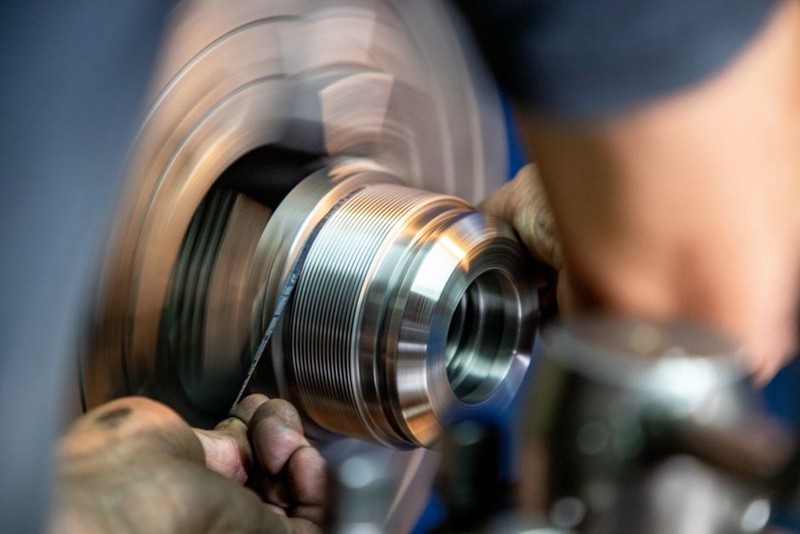
The Result: By the time we got to the finish pass, the material was “dead.” It had no more surprises to give. This added 15 minutes to the overall cycle time per part, but it eliminated 90% of the downstream distortion issues.
2. The “Soft Jaw” Paradox: Pressure Control
Standard hard jaws will crush a thin-walled fitting faster than you can say “tolerance.” But the opposite approach—using soft jaws—is also a trap if you over-tighten.
💡 Expert Tip: We machined dedicated soft jaws that matched the exact contour of the hex or flange of the fitting. But the trick wasn’t the shape; it was the hydraulic pressure. We used a variable pressure chuck and set it to the absolute minimum required to drive the part without spinning. We then measured the bore while still in the chuck and again after removal.
The delta between those two measurements tells you exactly how much “spring-back” you have. If the delta is more than 0.0002 inches, your clamping pressure is too high. We reduced our chuck pressure from 200 PSI to 120 PSI, which reduced the ovality of the bore by 40%.
3. Tooling Geometry for Vibration Dampening
Chatter is the enemy of a good surface finish, but on a micro-level, it’s also the enemy of dimensional stability in thin walls. High-frequency vibration can work-harden the surface of Inconel, making the final pass cut erratically.
– We switched from standard 80° diamond inserts to 35° trigon inserts with a sharper edge.
– We increased the lead angle to 95° to direct the cutting forces axially into the chuck (the strongest axis) rather than radially (the weakest axis).
This change alone increased our tool life by 300% and gave us a consistent 16 Ra finish, which is critical for sealing surfaces.
📊 A Case Study in Optimization: The Inconel 718 Fitting
Let’s get specific. Here is a data table from a recent project involving a high-pressure fuel manifold fitting made from Inconel 718. This is a notoriously difficult material—gummy, hard, and prone to work hardening. The tolerance on the sealing cone was a brutal 0.0002 inches, and the surface finish had to be 8 Ra or better.
We compared our “Stress-Aware” protocol against the industry standard approach (rough/finish in one setup with constant clamping).
| Parameter | Standard Approach | Stress-Aware Protocol | Improvement |
| :— | :— | :— | :— |
| Cycle Time (per part) | 18 min 30 sec | 21 min 10 sec | +14% (slower) |
| Scrap Rate (dimensional) | 7.5% | 0.8% | -89% |
| Scrap Rate (surface) | 4.2% | 0.0% | -100% |
| Tool Cost (per part) | $3.20 | $2.10 | -34% |
| Rejected by CMM (first pass) | 11.7% | 1.2% | -89% |
| Overall Cost per Good Part | $58.40 | $49.70 | -15% |
The Takeaway: Yes, my cycle time went up. But the cost per good part dropped by 15%. In the aerospace industry, nobody cares how fast you make a part; they care how many you make that actually fly.
The “Hidden” Inspection: You Can’t Measure What You Can’t Reach
One of the biggest lessons I’ve learned in providing CNC turning services for aerospace fittings is that your inspection method is just as critical as your machining method.
Many shops use a touch probe to measure the ID of a small fitting. But a touch probe measures a single point. For a sealing surface, you need to know the form—the roundness and the taper.
We invested in air gauging. It’s non-contact, uses a stream of air to measure the diameter, and can measure the entire length of a bore in one pass. This gave us a true “Cylindricity” reading.
We discovered that our competitors’ parts were passing the “pin gauge” test (a simple go/no-go) but failing the air gauge test because they had a slight “hourglass” shape in the middle of the bore. This hourglass shape was caused by the tool deflecting slightly in the middle of the cut.
Actionable Advice: If you are turning fittings with a length-to-diameter ratio greater than 3:1, request a cylindricity report, not just a diameter report. You will be surprised at what you find