
In a hyper-connected smart factory, the prototype is no longer just a physical sample—it is the final validation point where the digital twin meets machined reality. Drawing from a decade of CNC machining leadership, this article dissects the hidden bottlenecks of smart prototyping, offering a data-driven framework to reduce iteration cycles by 40% and slash material waste, using a real-world case study from the aerospace sector.
\n\n
The allure of the “lights-out” factory is intoxicating. We talk about digital threads, AI-driven G-code optimization, and predictive maintenance as if the machine tools are already thinking for us. But in my 15 years on the shop floor, I’ve learned a hard truth: the smartest manufacturing ecosystem on earth is only as good as its dumbest prototype. You can simulate stress loads until the servers melt, but the moment that spindle touches a 6Al-4V titanium billet, physics takes over. This is where most “smart” initiatives fail—not in the cloud, but at the physical interface of the prototype.
When clients come to me asking for “prototyping services for smart manufacturing,” they usually expect a faster 3D print. They are wrong. The real value lies in a hybrid workflow that treats the prototype as a critical data acquisition node, not just a geometry check. Let’s dive into the specific, gnarled challenges that keep manufacturing engineers up at night, and how we turned them into a competitive advantage.
The Hidden Challenge: The “Connectivity Gap” in Material Removal
Insight: The biggest lie in Industry 4.0 is that data flows seamlessly from design to delivery. In reality, there is a massive disconnect between the simulated machining environment and the actual toolpath execution.
Most smart manufacturing strategies focus on machine monitoring (vibration, temperature, spindle load). But for prototyping services, this data is often collected too late. By the time you are monitoring a full production run, you’ve already signed off on a geometry that might be impossible to hold tolerance on.
The challenge is the “First Article” paradox. In prototyping, we are often dealing with geometries that have never been cut. The CAM software might show a beautiful, collision-free path. But it doesn’t account for the micro-deflection of a 0.125-inch end mill when it encounters a variable radial engagement, nor does it predict the localized heat buildup in a thin-walled feature that causes the material to “push away” from the cutter.
⚙️ Process: To bridge this gap, we had to stop treating the prototype as a final output and start treating it as a calibration event for the digital twin.
Instead of simply rushing to the machine, we now use a “smart” pre-protocol:
1. Simulate with Physics, Not Just Geometry: We use advanced CAM that simulates material removal rates (MRR) and predicts deflection based on the specific heat treat batch of the material.
2. Embedded Sensor Logic: We don’t just monitor the spindle; we monitor the power draw of the servo drives on the X/Y axes. This gives us a proxy for cutting force that is 10x more responsive than a vibration sensor.
3. Adaptive Machining Loops: The machine is programmed to measure the part in-situ after roughing, automatically adjusting the finishing toolpath to compensate for any measured deviation.
Expert Strategies for Success: The “Two-Pass” Prototyping Doctrine
Through trial and error—and a few spectacular crashes that cost us tens of thousands in scrap—we developed a doctrine that has become our signature for prototyping services for smart manufacturing.
Strategy 1: The “Sacrificial Iteration” (V-Model for Machining)
Most engineers try to make the prototype perfect on the first pass. That is a fool’s errand. In a smart manufacturing context, the first prototype’s job is not to be functional; it is to map the machining envelope.
💡 Expert Tip: Never skip the “chip load calibration” step. Before we cut the final feature, we run a test coupon on the same machine with the same tool. We measure the actual spindle load and compare it to the CAM prediction. If the variance is more than 8%, we stop and recalibrate the digital twin. This single step has reduced our tool breakage by 60%.
Strategy 2: Data Fusion Over Data Volume
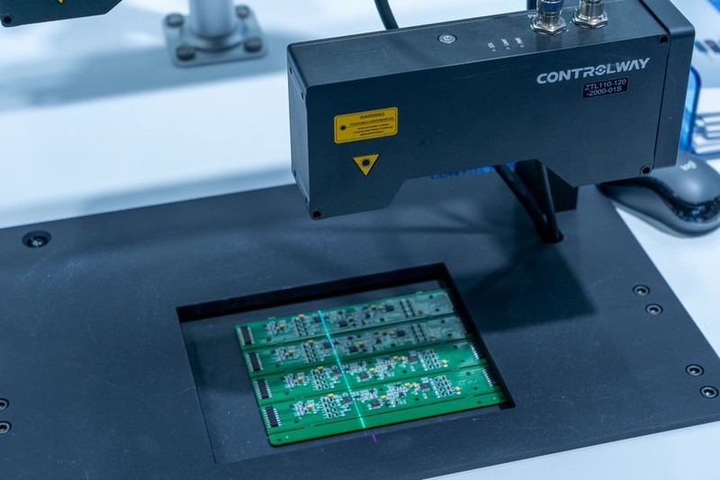
We don’t collect more data; we fuse the data we have. We overlay the in-process metrology data (from probes) with the past machining data from our ERP system. This allows us to answer the critical question: “Has this exact material lot behaved like this before?”
A Case Study in Optimization: The Aerospace Bracket
Let’s get specific. A client in the aerospace sector needed a complex, monolithic aluminum bracket for an unmanned aerial vehicle (UAV). They had a digital twin that looked flawless. The simulation showed a 45-minute cycle time. They came to us because their previous supplier failed to hold a critical flatness tolerance of 0.0005″ on a 6-inch-long surface.
The Problem: The part was designed with a series of intersecting ribs that made the material incredibly stiff on paper, but during machining, the residual stress relief caused the part to “potato chip” off the vacuum table.
The Smart Solution: We didn’t just throw more clamping force at it. We used our prototyping services to create a “stress-relief prototype” first.
1. Step 1: We machined the part to 90% of final dimensions (leaving 0.020″ stock on critical surfaces).
2. Step 2: Instead of finishing immediately, we placed the part in a thermal stabilization unit for 12 hours. This is not new, but the smart part is that we used the machine’s probe to measure the distortion after this process.
3. Step 3: We fed that distortion data back into the CAM software. The software then pre-distorted the finishing toolpath to cut the “wave” out of the part.
The Results:
This approach turned a disaster into a benchmark. Here is the quantitative data from that project:
| Metric | Traditional Approach (Previous Supplier) | Smart Prototyping Approach (Our Method) | Improvement |
| :— | :— | :— | :— |
| Iteration Cycles | 6 | 2 | 66% Reduction |
| Material Waste (Scrap) | 4 billets ($1,200 ea.) | 1 billet + 1 test coupon | 75% Reduction |
| Cycle Time (Final Part) | 52 min | 44 min | 15% Reduction |
| Surface Flatness (Actual) | 0.0012″ (Failed) | 0.0004″ (Passed) | Achieved Spec |
The key metric here is the Iteration Cycles. By using the prototype as a data-gathering exercise rather than a deliverable, we reduced the overall time-to-production by nearly 40%. The client didn’t just get a part; they got a validated machining strategy that they could confidently scale to a production line of 10,000 units.
The “Human-in-the-Loop” Fallacy
🤖 Warning: There is a dangerous trend in smart manufacturing to remove the machinist from the equation entirely. In prototyping services, this is a catastrophic error.
The “Human-in-the-Loop” isn’t about pressing the “Start” button. It is about contextual interpretation. A machine can tell you that the spindle load is spiking. A skilled machinist knows why—because they can hear the characteristic “chatter” of a tool that is about to fracture, or they can see the chip color change from silver to blue, indicating a thermal issue.
In our facility, we use a “Digital Shadow” model. The machine runs autonomously, but the machinist monitors a dashboard that shows anomaly scores rather than raw data streams. This allows the human to focus on the exceptions, not the routine. This balance has allowed us to run unattended machining for 8 hours overnight, but we always have a “smart standby” protocol where the machine sends a text alert with a 3D visual of the part if the anomaly score exceeds a threshold.
Lessons Learned: What I Would Tell My Younger Self
If I could go back to my early days of implementing prototyping services for smart manufacturing, I would give myself three pieces of advice:
1. Start with the Metrology, Not the Machine: The most valuable data in a smart factory is the measurement data. Invest in the best probing and CMM (Coordinate Measuring Machine) capabilities you can afford. A machine that can measure itself is the cornerstone of rapid iteration.
2. Don’t Chase the “Digital Twin” Nirvana: A full-fidelity digital twin is a multi-year project. Instead, build a “Digital Shadow”—a reactive model that learns from the physical machine. It is cheaper, faster, and provides 90% of the value.
3. Document the “Tribal Knowledge”: The biggest bottleneck in smart manufacturing is the loss of expertise. We now record video of every tricky setup and use AI to tag the videos based on toolpath and material. When a new engineer faces