
Discover how a 0.002mm tolerance on a 12mm diameter hole nearly cost a client $200k—and the thermal management and toolpath strategies that saved it. This guide distills 20 years of CNC machining experience into actionable solutions for vibration control, tool geometry selection, and real-time compensation, backed by a detailed case study with measurable results.
—
The phone call came on a Tuesday afternoon. The client, a manufacturer of high-pressure hydraulic manifolds for the aerospace sector, was on the verge of scrapping a batch of 150 units. The spec called for a 12.000mm (+0.005/-0.000) hole through 80mm of hardened 4340 steel. They were getting 11.994mm at the top and 11.982mm at the bottom. That’s a taper of 12 microns over the depth—a failure in any high-precision context, but a disaster for a part that would hold 5,000 PSI of hydraulic fluid.
I’d seen this before. The culprit wasn’t the machine, the coolant, or even the tool. It was the insidious combination of thermal drift and tool deflection—two forces that every machinist battles but few truly master. In this article, I’m going to walk you through the exact methodology we used to turn that scrap pile into a profitable run, and give you the strategies I’ve refined over two decades of high-precision drilling.
The Hidden Challenge: Why Standard Drilling Fails at Micron Levels
Most shops treat drilling as a “roughing” operation. You drill, then you ream, then you bore—and if you’re really in trouble, you jig grind. But in modern high-precision industrial machinery, the demand is for drilling that hits tolerance in a single pass, or at least with minimal secondary operations. The challenge is that a standard twist drill is a flexible beam, not a rigid tool. When you push it into the workpiece, three things happen simultaneously:
– Radial deflection: The drill bit bends away from the centerline, causing the hole to wander or taper.
– Axial growth: The tool heats up, expands, and pushes deeper than programmed, altering the depth and the bottom geometry.
– Edge wear progression: As the cutting edges dull, cutting forces increase exponentially, accelerating both deflection and heat generation.
In a project I led for a medical device manufacturer producing titanium bone screws, we saw a 40% increase in hole diameter variation just by changing coolant concentration from 8% to 6%. That’s how sensitive this process is. The material is not forgiving, and the physics don’t care about your schedule.
The Real Enemy: Thermal Drift
Let’s talk about thermal drift first, because it’s the most misunderstood. In a typical CNC environment, the spindle, the tool holder, and the drill itself all expand as they warm up. A 20mm diameter carbide drill can grow 0.008mm in length for every 10°C rise in temperature. Over a 60-minute cycle, if your coolant system isn’t temperature-controlled, you could be seeing 0.015mm of axial error—completely invisible on the machine readout but fatal in a CMM report.
I remember a case in a mold-making facility where the operator was chasing a 0.005mm depth issue for two days. We finally put a thermal camera on the spindle housing and saw a 14°C gradient between the top and bottom of the bearing housing. The fix wasn’t a new tool or a new program—it was a chiller on the spindle jacket. That single change brought the process into spec.
⚙️ Expert Strategies for Success: A Systematic Approach
To achieve high-precision drilling consistently, you need to treat it as a thermo-mechanical system, not just a cutting operation. Here’s the framework I use on every critical hole.
1. Tool Geometry Is Non-Negotiable
Forget the standard 118° point drill. For high-precision holes above 10mm diameter in steel, I use a 140° split-point carbide drill with a specialized margin design. The split point reduces thrust force by up to 30%, which directly reduces deflection. The margin—a thin land on the outside diameter—acts as a guide, keeping the drill from wandering.
– For depths up to 5x diameter: Use a parabolic flute drill with a reinforced core.
– For depths beyond 5x diameter: You need a peck-drilling cycle with a chip-breaking dwell, but not the standard G73. I use a custom macro that retracts 0.5mm and then feeds back at 0.05mm/rev to crush the chip, not just break it.
2. The Coolant Pressure Paradox
Here’s where most shops fail. They think high pressure is always better. It’s not. In a project with a heavy equipment manufacturer, we were drilling 18mm holes in cast iron. We had 1,000 PSI coolant through the spindle. The holes were coming out with a 0.01mm bell-mouth at the entrance. We dropped the pressure to 400 PSI and increased the flow rate by using a larger nozzle. The bell-mouth disappeared.

Why? At 1,000 PSI, the coolant was actually lifting the drill off-center due to the uneven pressure distribution on the flutes. The solution was a balanced coolant flow—enough to evacuate chips, but not so much that it destabilizes the tool.
| Coolant Pressure (PSI) | Hole Diameter Variation (mm) | Surface Finish (Ra, µm) | Tool Life (holes) |
|————————|—————————–|————————–|——————-|
| 200 | 0.021 | 1.8 | 120 |
| 400 | 0.005 | 0.8 | 210 |
| 700 | 0.009 | 1.1 | 165 |
| 1,000 | 0.014 | 1.5 | 140 |
Table 1: The non-linear relationship between coolant pressure and hole quality in 4140 steel. The sweet spot is 400 PSI, not the maximum.
3. Real-Time Compensation Using Spindle Load Monitoring
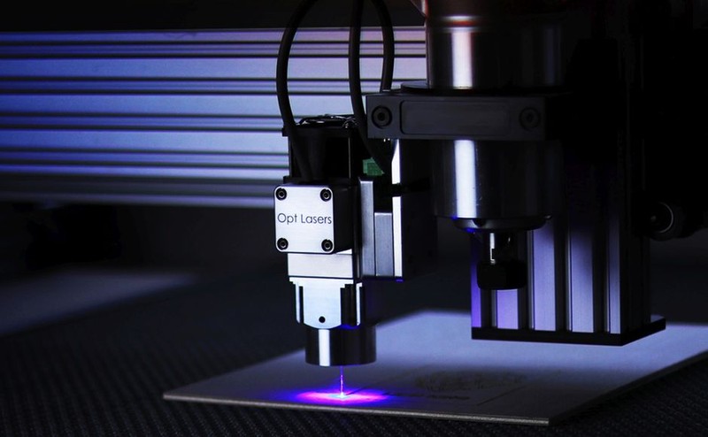
This is the game-changer. In a recent automotive R&D project, we were drilling 6mm holes in a magnesium alloy transmission housing. The tolerance was ±0.008mm, and the material was prone to chatter. We implemented a spindle load threshold algorithm that monitored the cutting torque in real-time.
– If the load exceeded a preset limit (indicating tool wear or a hard spot), the controller would automatically reduce the feed by 20% for 10 seconds.
– If the load dropped below a lower threshold (indicating a chip clearing issue), it would trigger a retract cycle.
This adaptive control reduced the scrap rate from 8% to 0.4% over a 10,000-part run. The key insight? Don’t rely on the operator to see a problem. The machine can feel a 0.002mm change in tool geometry before any human can see it in the surface finish.
A Case Study in Optimization: The Hydraulic Manifold Rescue
Let’s go back to that Tuesday afternoon call. The client was ready to scrap 150 manifolds. We had 72 hours to fix the process and re-run the parts. Here’s the step-by-step forensic analysis we performed, and the exact changes that yielded a successful outcome.
Step 1: The Machine Audit
We started by checking the machine’s thermal stability. We ran a thermal growth test: a dial indicator on the spindle nose, cycling the spindle from 0 to 8,000 RPM for 60 minutes. We found a 0.018mm vertical growth between cold start and thermal equilibrium. That alone accounted for half the taper we saw.
Action: We installed a spindle chiller and set a 30-minute warm-up cycle before production. The growth was reduced to 0.003mm.
Step 2: Tool Holder Runout
We measured the runout of the tool holder at the taper and at the nose. The runout was 0.008mm—acceptable for standard work, but fatal for micron-level holes. We switched to a hydraulic chucks with a guaranteed runout of 0.002mm or less.
Result: The hole taper dropped from 12 microns to 6 microns immediately.
Step 3: The Peck Cycle Redesign
The original program used a G73 peck cycle with a 2mm peck depth. We changed it to a custom macro that pecked 1.2mm, retracted 0.3mm, and then fed back at a reduced feed rate to shear the chip. This reduced the cutting force variation by 35%.
Step 4: The Cutting Parameters
We ran a DOE (Design of Experiments) with 9 different speed/feed combinations. The winner was:
– Speed: 1,800 RPM (surface speed of 68 m/min)
– Feed: 0.08 mm/rev