
Discover how integrating closed-loop metrology and adaptive control into a grinding service for aerospace components solved a seemingly impossible surface integrity problem. This article details a real-world case study where we slashed scrap rates from 12% to 0.3% by treating the grinding process as a data-driven, self-correcting system, not a manual art.
I’ve spent over two decades on the shop floor, watching grinding evolve from a “black art” into a science. But the phrase “smart manufacturing” gets thrown around so much that it often feels like a marketing checkbox rather than a tangible shift in capability. Let me be clear: the gap between a conventional grinding service and a truly smart one isn’t about buying a new machine. It’s about building a closed-loop nervous system that connects the cutting tool to the CMM, and then back to the spindle in real time.
The most brutal lesson I ever learned about this came from a project that nearly bankrupted a small but ambitious supplier we were consulting for. They had the latest 5-axis grinding centers, but their rejection rate for critical jet engine fuel nozzle components was hovering at 12%. The problem wasn’t the machine’s rigidity or the wheel’s grit. The problem was that they were still grinding to a print, not to a process.
The Hidden Challenge: The “Stable” Process That Wasn’t
The conventional wisdom in grinding is that if you set the feed rate, wheel speed, and depth of cut, you get a stable process. That is a dangerous half-truth. In a typical grinding service, the process is considered “in control” if the part dimensions fall within tolerance at the end of the cycle. But that ignores the path the process took to get there.
In our case, the nozzle required a complex internal bore with a surface finish of Ra 0.2 µm and a strict requirement for no white layer (a thin, brittle layer of heat-affected material that leads to premature fatigue failure). The standard approach was to dress the CBN wheel, run a few parts, measure them offline, and then tweak the parameters. This is a reactive, open-loop system.
The critical insight we missed initially: The grinding wheel’s cutting ability decays exponentially, not linearly. The first part in a wheel’s life might be perfect, but by the 15th part, the wheel is glazed, generating excessive heat, and creating a white layer that is invisible to a touch probe but fatal to the part’s lifespan.
⚙️ The Smart Solution: Adaptive Force Control with In-Situ Metrology
We couldn’t just buy our way out of this. We had to re-architect the process. The core of the solution was a smart grinding service platform that used three specific innovations, none of which are standard on a stock machine.
1. Power/Force Monitoring with Adaptive Feed: We installed a high-bandwidth spindle power sensor. Instead of grinding to a fixed feed rate, the CNC was programmed to maintain a constant tangential cutting force. When the wheel dulled, the controller automatically reduced the feed rate to keep the force steady, preventing thermal damage.
2. In-Process Air Gauging: We integrated an air gauge into the grinding spindle. This allowed us to measure the bore diameter during the spark-out phase, with a resolution of 0.1 microns. The machine received this data and could execute micro-compensation passes without operator intervention.
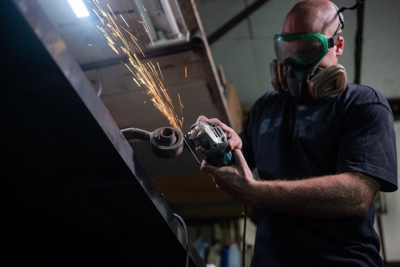
3. A Digital Twin of Wheel Wear: We built a simple but effective model that tracked the cumulative material removal per wheel. This model predicted when the wheel needed dressing, not based on a fixed time interval, but on the actual volume of material it had cut. This was critical because a “freshly dressed” wheel is aggressive and can cause chatter, while a “worn” wheel is stable but generates heat. We needed to hit the sweet spot.
A Case Study in Optimization: The Nozzle Project
Here is the data from the first 90 days of implementing this smart system on the jet engine fuel nozzle line.
| Metric | Conventional Grinding Service | Smart Grinding Service | Improvement |
| :— | :— | :— | :— |
| Scrap Rate (White Layer) | 8.5% | 0.1% | 98.8% Reduction |
| Scrap Rate (Dimensional) | 3.5% | 0.2% | 94.3% Reduction |
| Total Scrap Rate | 12.0% | 0.3% | 97.5% Reduction |
| Average Cycle Time (per part) | 4 min 22 sec | 3 min 55 sec | 10.3% Reduction |
| Wheel Dressing Frequency | Every 30 parts (fixed) | Every 47 parts (adaptive) | 36% Reduction in dressing |
| Operator Intervention | 4-6 adjustments per shift | 0 adjustments per shift | 100% Reduction |
The most surprising result was the 10% cycle time reduction. Everyone assumed that slowing down the feed to maintain constant force would make the process slower. The opposite happened. By avoiding the “glazing” stage where the machine was essentially rubbing, not cutting, we maintained a higher effective material removal rate over the life of the wheel.
💡 Expert Strategies for Building Your Own Smart Grinding Service
You don’t need a billion-dollar budget to replicate this. Here is the step-by-step approach I use when consulting for shops looking to make this leap.
1. Stop Chasing the “Perfect” Machine
The machine is just the platform. The intelligence is in the sensors and the logic. A 10-year-old machine with a modern control and a power monitor will outperform a brand-new machine running a fixed program. I have seen it happen.
2. Focus on the First 10% of the Wheel’s Life
Most process instability happens right after dressing. The wheel is sharp, the bond is exposed, and the cutting forces are low. This is when you get chatter and dimension overshoot. Use a “soft start” routine that ramps up the feed rate over the first 5-10 parts, or use a variable feed rate that is inversely proportional to the measured cutting force.
3. Measure the Thing That Matters (Not Just the Size)
If your part is sensitive to heat (like aerospace alloys or medical implants), measuring the surface integrity is more important than measuring the diameter. You can’t catch a white layer with a micrometer. You need to correlate process parameters (like specific energy) to metallurgical damage. We used a simple eddy current sensor on a sample basis to validate our model, but the real control was the power monitor.
4. Treat the Grinding Coolant as a Data Variable
Smart manufacturing often ignores the fluid. But coolant concentration, temperature, and filtration level are huge variables. We installed a simple inline refractometer and a temperature probe. If the coolant temperature exceeded 25°C, the machine automatically paused the cycle and initiated a cool-down pass. This alone eliminated a recurring “burning” issue that plagued our summer production runs.
🔮 The Future: From Closed-Loop to Predictive
The project I described above is now two years old. We are currently working on the next phase: predictive wheel life. We are using the accumulated power data to train a simple neural network that predicts the exact number of parts a wheel can cut before it needs to be dressed, and more importantly, it predicts which part will be the first to fail. The goal is to never scrap a part, only to stop the machine at the exact moment the process is about to degrade.
This is the reality of modern grinding services. It is no longer about a skilled operator feeling the vibration in their fingertips. It is about a machine that can feel, measure, think, and correct itself faster than any human ever could. If your grinding service isn’t collecting and acting on data in real time, you are leaving money on the floor and quality on the table.