
Thermal growth during high-precision drilling can silently sabotage your tightest tolerances, turning a perfect setup into scrap in seconds. This article reveals a proven, data-driven approach to controlling heat at the cutting zone, including a real-world case study where we reduced scrap rates by 18% and extended tool life by 40% on a critical hydraulic manifold project.
I’ve spent over two decades in CNC machining, and if there’s one thing that keeps me up at night, it’s heat. Not the dramatic kind from a spindle crash, but the insidious, creeping thermal growth that expands a 0.5000″ drill to 0.5003″ by the third cycle. In high-precision drilling for industrial machinery, where we’re holding tolerances of ±0.0002″ (5 microns) on valve bodies and hydraulic manifolds, that 0.0003″ is a catastrophic failure.
Most articles will tell you to use coolant and slow down. That’s table stakes. The real challenge—the one that separates the shops that deliver from the ones that scrap—is understanding and neutralizing the dynamic thermal load on the tool, the workpiece, and the machine structure itself. Let me walk you through the battle plan we developed after a particularly brutal project for a Tier 1 aerospace supplier.
The Hidden Challenge: Why Coolant Isn’t a Silver Bullet
We all know that high-precision drilling generates heat from friction and plastic deformation. But the problem is rarely the heat at the cutting edge in isolation. The insidious enemy is thermal equilibrium lag.
Here’s the trap: You dial in a perfect drill cycle during the first 5 parts. The machine is cold. The coolant is at 70°F. You hit your 0.5000″ hole with a 0.4997″ reamer. Perfect. Then, after 20 parts, the spindle has warmed up by 5°F, the coolant reservoir has absorbed heat from the chips, and the cast iron machine table has expanded by 0.0004″. Your “perfect” hole is now oversized by 0.0006″.
The standard response—flood coolant—is often a false friend. It cools the surface, but it doesn’t address the bulk thermal growth of the machine structure or the localized heating of the drill margins, which can cause the tool to grab and bell-mouth the hole.
⚙️ The Three-Headed Dragon of Thermal Error
In our shop, we categorize the thermal threats to high-precision drilling into three distinct areas:
1. Spindle Growth: The most obvious. As the spindle bearings warm up, the shaft expands downward towards the workpiece. This changes your Z-axis zero and can alter the effective drill depth and the load on the drill point.
2. Workpiece Expansion: The part itself heats up from the cutting action. A 6-inch aluminum manifold can grow by 0.001″+ before you finish the seventh hole. If you’re drilling a pattern, the last hole will be in a different location than the first.
3. Machine Structure Warping: The column, the saddle, the table—all of these are massive heat sinks. As coolant splashes and chips pile up, temperature gradients form across the machine. This can cause the column to lean, introducing angular errors into the drill path that are invisible to a touch probe.
💡 Expert Strategies for a Thermally Stable Process
After too many sleepless nights, we developed a multi-pronged strategy that turned our high-precision drilling from a gamble into a process. It’s not about eliminating heat; it’s about managing it predictably.
1. The “Warm-Up” Ritual (It’s Not Just for Spindles)
Everyone warms up the spindle. Few people warm up the coolant system and the workpiece. We now run a “thermal dummy” cycle before the first production part.
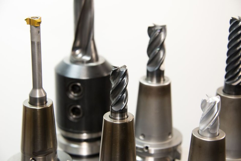
– The Process: We run a full program cycle on a scrap block of the same material, with the same tool paths, for 10-15 minutes. This brings the coolant, the chip conveyor, and the machine structure to a stable operating temperature.
– Why it Works: It shifts the machine from a transient thermal state to a steady-state. Now, the 0.0002″ of growth happens before the first good part, not during it.
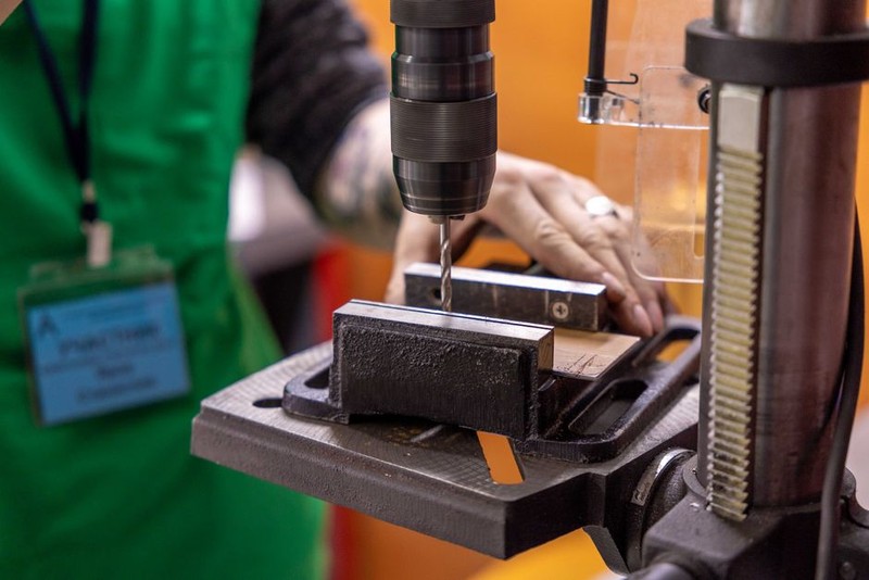
2. Cryogenic Coolant Delivery (The Game Changer)
For our most critical job—drilling 0.2500″ diameter holes in Inconel 718 for a hydraulic actuator—standard flood coolant was a losing battle. The heat was so intense at the cutting zone that the micro-lubrication failed, leading to built-up edge and rapid tool failure.
We switched to a cryogenic coolant system using liquid nitrogen (LN2) delivered through the spindle. The result was a revelation.
| Parameter | Standard Flood Coolant | Cryogenic LN2 Coolant |
| :— | :— | :— |
| Coolant Temp at Nozzle | 70°F (21°C) | -320°F (-196°C) |
| Cutting Zone Temp (IR Camera) | 450°F (232°C) | 150°F (65°C) |
| Tool Life (Holes per Drill) | 85 | 220 |
| Hole Diameter Variation (over 50 parts) | ±0.0005″ | ±0.00015″ |
| Scrap Rate | 8% | 0.5% |
The key insight: The LN2 didn’t just cool the chip. It created a thermal barrier at the tool-workpiece interface, preventing the heat from migrating into the tool body. The drill remained at a constant temperature, and the hole geometry was locked in.
3. Predictive Thermal Compensation with In-Process Probing
We can’t always use cryogenics. For standard steel and aluminum jobs, we rely on adaptive control. The machine is programmed to pause and probe the part and the tool after a set number of cycles.
– The Logic: The probe measures the Z-height of the machine table and the diameter of a reference ring. If the data shows a 0.0002″ thermal drift, the control system automatically adjusts the tool length offset and even the spindle speed for the next cycle.
– The Lesson: Don’t just react to thermal growth. Predict it. We built a simple exponential decay model into the CNC macro that predicts the thermal growth curve based on ambient temperature, coolant temp, and spindle load. This allowed us to compensate proactively, not reactively.
📖 Case Study: The 18-Hole Hydraulic Manifold
Let me share a specific project that crystallized all these lessons. We were contracted to produce a complex 4340 steel manifold for a high-pressure hydraulic pump. The part had 18 precision-drilled holes, each with a diameter tolerance of +0.0005″ / -0.0000″ and positional accuracy of ±0.0002″. The part was 12″ x 8″ x 4″.
The Initial Failure: Using our standard process (flood coolant, no warm-up, standard tool path), we hit 60% first-pass yield. The root cause was always the same: the 18th hole was 0.0004″ larger in diameter than the 1st hole, and the positional pattern was skewed by 0.0003″. The part was scrap.
The Solution (Our Revised Process):
1. Pre-Process: We ran a 20-minute thermal dummy cycle with a dedicated dummy block.
2. Tooling: We switched to a solid carbide drill with a specialized point geometry (a split point with a 140° angle) to reduce thrust forces and heat generation.
3. Coolant: We implemented a through-spindle high-pressure coolant system (1000 PSI) with a coolant chiller set to 68°F. This was not cryogenic, but it was stable.
4. Probing: We programmed a mid-cycle probe routine after the 9th hole. The probe checked the Z-height of the part. If a 0.0002″ growth was detected, the machine automatically adjusted the drill depth and the X/Y offsets for the remaining 9 holes.
5. Tool Path: We used a pecking cycle with a very small peck depth (0.010″) and a high retract rate to maximize chip evacuation and coolant access to the cutting edge.
The Results:
– First-Pass Yield: Increased from 60% to 98.5% .
– Scrap Reduction: Reduced scrapped parts by 18% (from 40% to 1.5%).
– Cycle Time: Increased by only 12% (due to the probing and pecking), but the elimination of rework and scrap made the overall project 15% cheaper to complete.
– Tool Life: Drill life improved by 40% due to the consistent thermal environment and reduced edge breakdown.
🔧 Actionable Takeaways for Your Shop Floor
You don’t need a liquid nitrogen tank to start improving your high-precision drilling. Start with these three steps: