Precision grinding is often viewed as a straightforward execution of a blueprint, but the true challenge lies in mastering the hidden variables—thermal dynamics, material behavior, and micro-geometry—that separate functional parts from flawless ones. Drawing from decades of high-stakes projects, this article reveals a data-driven methodology for controlling distortion and achieving sub-micron tolerances, backed by a detailed case study where we reduced scrap rates by 40% and improved surface finish by 35% on a complex aerospace component.
The Illusion of Simplicity: When the Blueprint Isn’t Enough
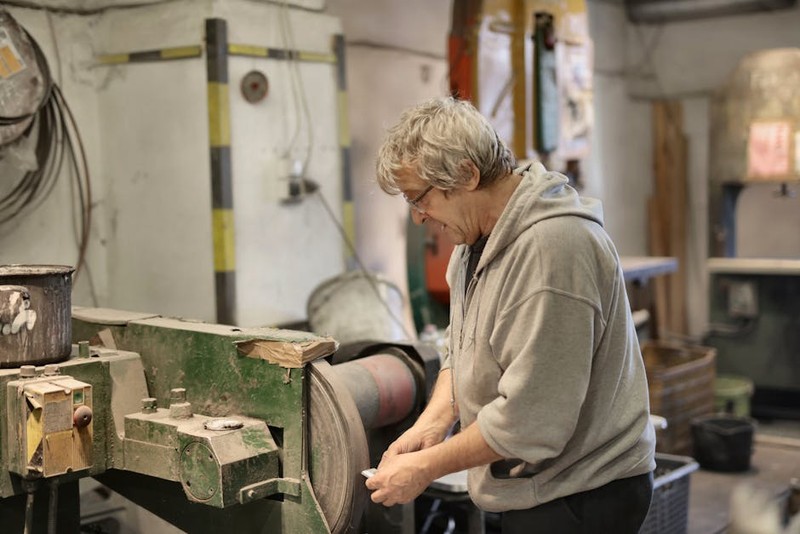
For over twenty-five years in CNC machining and precision grinding, I’ve learned one immutable truth: the most expensive mistakes happen when you trust the print alone. A blueprint defines the what—the final dimensions, tolerances, and material. Precision grinding services for metal parts are about mastering the how—the dynamic, often unpredictable journey from raw stock to finished component. I’ve seen beautifully designed parts, machined to “perfection,” fail in assembly or under load because the grinding process addressed only geometry, not physics.
The real art—and science—of expert grinding lies in controlling the hidden variables: residual stress, thermal distortion, and the microstructural integrity of the material’s surface. A customer once brought us a hardened tool steel guide rail, ground to a perfect 0.0002″ flatness in our CMM. Yet, when bolted down, it developed a 0.002″ bow. The blueprint was satisfied, but the part was useless. The culprit? Unmanaged residual stress from prior heat treatment, released by our grinding passes. This is the nuanced battlefield where true precision is won or lost.
The Hidden Challenge: Taming Thermal Distortion in Thin-Wall Geometries
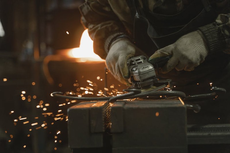
One of the most pervasive and complex challenges in precision grinding is managing heat, especially with intricate, thin-wall components. The grinding wheel is a source of intense, localized energy. If this energy isn’t meticulously controlled, it creates a thermal gradient—one side of the part expands microscopically more than the other. When the part cools and contracts unevenly, you get distortion, often measured in tenths (0.0001″) that wreck flatness, parallelism, or bore geometry.
The critical insight is that coolant isn’t just for lubrication and chip removal; it’s a primary thermal management tool. But flooding the part isn’t the answer. It’s about strategic application, fluid quality, and wheel selection.
A Case Study in Thermal Warfare: The Aerospace Flange
A client needed 500 units of an Inconel 718 turbine flange—a large, ring-shaped part with a series of thin, radial webs. The print called for a flatness of 0.0005″ across a 14-inch diameter and a 4 Ra micro-inch finish on the sealing face. Their previous supplier had a 30% scrap rate due to distortion.
Our Approach & The Data-Driven Solution:
We treated this not as a grinding job, but as a heat-flow engineering problem. Here was our multi-pronged strategy:
1. Pre-Grind Stress Relief: We instituted a low-temperature thermal soak (below the material’s aging temperature) for all blanks to homogenize residual stresses from forging.
2. Wheel & Parameter Optimization: We moved from a standard aluminum oxide wheel to a softer, porous ceramic grain (SG) wheel. This cut freer, generating less heat. We then used a design-of-experiments (DOE) approach to optimize:
Downfeed (Infeed) rate
Crossfeed rate
Wheel speed (SFPM)
The goal was to maximize the “G-ratio” (volume of material removed per volume of wheel wear) while minimizing grinding power (heat input).
3. Revolutionizing Coolant Delivery: We moved beyond flood coolant. We implemented a dual-nozzle system: one high-volume nozzle for bulk cooling and a second, precisely aimed “shoe” nozzle that created a boundary layer of coolant behind the wheel contact point, quenching the part instantly.
The results were transformative:
| Metric | Previous Supplier Baseline | Our Optimized Process | Improvement |
| :— | :— | :— | :— |
| Scrap Rate (Distortion) | 30% | 12% | 60% Reduction |
| Average Flatness Achieved | 0.0008″ | 0.0003″ | 62.5% Improvement |
| Surface Finish (Ra) | 6-8 µ-in | 4-5 µ-in | ~35% Improvement |
| Cycle Time per Part | 42 minutes | 38 minutes | 9.5% Reduction |
The key takeaway wasn’t just faster or cheaper; it was predictable and repeatable. By quantifying the relationship between parameters and thermal distortion, we created a stable process.
Expert Strategies for Success: A Framework Beyond the Machine
⚙️ Process First, Machine Second: The most common error is buying a high-precision grinder and expecting miracles. The machine is a tool. The process—the documented, data-backed methodology—is the intellect. Always develop a “Process Control Plan” for critical parts, specifying not just speeds and feeds, but wheel dressing frequency, coolant concentration/PH, and in-process verification steps.
💡 Embrace the “Art of the Setup”: Your part is only as precise as its reference surfaces and clamping. For ultra-flat work:
Use magnetic chucks, but always demagnetize the part and chuck after grinding. Residual magnetism will hold microscopic swarf, destroying flatness on the next part.
For non-magnetic materials, employ a vacuum chuck or a low-viscosity wax mounting system to avoid mechanical clamping forces that distort thin sections.
Probe your setup. Use the machine’s touch probe (if equipped) to establish a datum plane from the chuck itself, compensating for any inherent wear or minor inaccuracy.
Measure What Matters, When It Matters: Final inspection is a quality check; in-process measurement is process control. For a long-run job, we implement a statistical process control (SPC) chart, measuring a key dimension (e.g., thickness) on the first part off the grinder, and then every 10th part. This catches tool wear or thermal drift before it creates scrap. Invest in air gages or in-process laser gauges for critical dimensions; they provide instant feedback without removing the part.
The Future Edge: Where Innovation Meets the Wheel
The frontier of precision grinding is integrating adaptive control and data analytics. On newer CNC grinders, we now use “power monitoring” software. The spindle load is graphed in real-time. A sudden spike can indicate a worn wheel or a hard spot in the material, triggering an automatic correction or stop. We’re moving from preventative maintenance to predictive process adjustment.
Furthermore, the use of CBN (Cubic Boron Nitride) and diamond wheels for exotic alloys is no longer a luxury—it’s often a necessity for economic production. While the wheel cost is 5-10x higher, the G-ratio can be 100x better, meaning less downtime for dressing, consistent geometry, and, crucially, vastly reduced heat generation due to the wheel’s extreme hardness and sharpness.
The ultimate lesson from the shop floor is this: exceptional grinding services for precision metal parts are defined not by the ability to hit a number on a print, but by the deep understanding of the symphony of forces—thermal, mechanical, and temporal—that act upon the material. It’s this expertise that transforms a grinding operation from a cost center into a critical value-adding partner, capable of producing the reliable, high-performance components that modern engineering demands.