CNC turning for rapid prototyping is often misunderstood as just a faster way to make a part. The real challenge lies in designing for manufacturability from the first CAD click. This article dives into the expert strategies for leveraging CNC turning to create functional, test-ready prototypes that accelerate development and de-risk production, based on hard-won lessons from the shop floor.
The Prototype Paradox: Speed vs. Substance
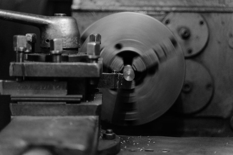
In my two decades of running a precision machining shop, I’ve seen a fundamental shift. Clients no longer want just a “looks-like” prototype; they demand a “works-like” prototype. The pressure of rapid development cycles has pushed CNC turning for rapid prototyping beyond its traditional role. It’s no longer just about visual validation—it’s about functional testing, assembly verification, and gathering real-world performance data before committing to high-volume production.
The paradox? To move fast, you often have to think slow. Rushing a design to the lathe without considering the nuances of the turning process is the fastest route to a prototype that fails its test, misleading your entire R&D team. The most common pitfall I encounter is the disconnect between the designer’s vision and the machinist’s reality. A beautiful, complex CAD model might be a nightmare to fixture, require exotic tooling, or have tolerances that are unnecessarily tight for the prototype phase, inflating cost and lead time without adding value.
The Expert’s Blueprint: Designing for the Lathe from Day One
The secret to successful CNC turning prototyping isn’t a secret at all—it’s a disciplined, collaborative approach. Here’s how we bridge the gap between design intent and manufactured part.
Strategy 1: The “Prototype-Specific” Design Review
Before any G-code is generated, we insist on a design review focused solely on prototype objectives. We ask:
What is this prototype’s primary job? (e.g., fit check, fluid flow test, structural load?)
Which features are critical for that test? Only these get the tight tolerances.
Which features can be simplified? Can that internal undercut be eliminated? Can we use a standard drill size instead of a custom one?
In a recent project for a medical device startup, the design called for a titanium housing with a complex internal helical channel. For production, it would be EDM’d. For the prototype, we suggested machining the channel as a series of straight, stepped bores that approximated the volume and flow path. This change cut machining time from 18 hours to 4.5 hours and cost by 65%, while still allowing the engineers to test the core fluid dynamics principle.
⚙️ Strategy 2: Strategic Material Selection
Material choice for a prototype is a critical, often overlooked, lever. While “production-equivalent” material is ideal, it’s not always pragmatic.
Consider this data from our shop, comparing two common requests:
| Material | Cost Factor | Machinability Rating (1-10, 10=Best) | Lead Time | Best For Prototype When… |
| :— | :— | :— | :— | :— |
| 6061 Aluminum | 1.0 (Baseline) | 9 | 3-5 days | 80% of functional prototypes. Excellent for fit, form, basic function. |
| 304 Stainless Steel | 2.5 | 5 | 5-7 days | Testing corrosion resistance or higher strength. |
| Titanium 6Al-4V | 7.0 | 3 | 7-10+ days | Only if absolutely necessary. For testing in extreme environments. |
| Delrin (POM) | 0.8 | 10 | 2-4 days | Excellent for wear testing, insulating components, or where lubrication isn’t desired. |
The expert move: We often recommend machining the initial design in aluminum, even if the production part will be steel. It’s faster, cheaper, and exposes design flaws with far less financial pain. Once the design is validated, then you make the “hero” prototype in the final material.
A Case Study in Pragmatic Precision: The Over-Engineered Sensor Housing

A client brought us a design for an aerospace sensor housing. The drawing called out ±0.0005″ (0.0127mm) tolerances on all major diameters and a surface finish of 8 µin Ra. The lead time request was “as fast as possible.”
The Challenge: These specs were appropriate for the final, high-performance assembly but were massive overkill for a prototype whose sole job was to verify the PCB fit and sensor alignment. Achieving those tolerances would require multiple finishing passes, specialized tooling, and meticulous in-process measurement, tripling the time and cost.
Our Solution: We scheduled a 15-minute call with their lead engineer. We asked: “What does this prototype need to do?” The answer: “Make sure the board slides in and the mounting holes line up.”
The Outcome: We agreed to:
1. Hold the critical bore for the PCB at ±0.001″ and the mounting holes at true position 0.002″.
2. Relax all other non-critical features to ±0.005″.
3. Specify a 32 µin Ra finish, which is still excellent but achievable in a single turning operation.
The results were transformative:
Machining Time Reduced: From ~2.5 hours to 45 minutes per part.
Cost Savings: 40% reduction per prototype unit.
Lead Time: Parts delivered in 3 days instead of 10.
Client Feedback: “The prototypes performed their function perfectly. We now have a more rational tolerance scheme for our production drawings.”
This case underscores a core principle: The most precise prototype is not always the best prototype. The right prototype is the one that answers your key questions reliably and efficiently.
💡 Actionable Takeaways for Your Next Project
1. Initiate a “DFP” (Design for Prototyping) Conversation Early. Bring your machinist into the loop during the conceptual design phase. Their insight on fixturing, tool access, and material behavior is invaluable.
2. Tolerances are a Cost Dial, Not Just a Quality Metric. Challenge every tight tolerance. If it’s not critical for the prototype’s function, loosen it. You can always tighten it up in the next iteration.
3. Embrace Iterative Prototyping. Plan for Proto v1 (basic function), v2 (refined design), and v3 (production-intent). This staged approach de-risks the project and manages budget effectively.
4. Consider Secondary Operations Realistically. A beautiful turned part might need milling, threading, or anodizing. Factor these into your timeline. Sometimes, designing a part as two simpler turned components that assemble can be faster for prototyping than one monolithic, complex part.
The Future is Integrated
The frontier of CNC turning for rapid prototyping is its integration with digital twins and in-process metrology. On our newer lathes, probe cycles can automatically measure a critical dimension mid-job and adjust tool offsets, guaranteeing the prototype is within spec the first time. This data feeds back directly to the designer, closing the loop between the digital model and the physical part faster than ever.
Ultimately, mastering CNC turning in the prototyping phase is about mindset. It’s a collaborative engineering tool, not just a procurement step. By designing with the lathe in mind, you transform your prototype from a mere placeholder into the most informative and cost-effective step in your product development journey. You don’t just get a part faster; you get to a better product, faster.